Slide mold paver provided with postposed mold mechanism

A technology of slip-form paver and mold mechanism, which is applied in the direction of roads, road repairs, roads, etc., and can solve problems such as restricting the application of slip-form paver, consuming a large amount of manpower, and affecting construction quality

Pending Publication Date: 2018-08-07
JIANGSU SIMING ENG MACHINERY
View PDF0 Cites 3 Cited by
  • Summary
  • Abstract
  • Description
  • Claims
  • Application Information

AI Technical Summary

Problems solved by technology

For rural roads and country roads and other pavement projects that do not have soil shoulders, it is necessary to manually repair the space occupied by the crawler belt, which affects the construction quality and consumes a lot of manpower.
The Application of Slipform Paver in Small Pavement Engineering is Restricted

Method used


Image

  • Slide mold paver provided with postposed mold mechanism
  • Slide mold paver provided with postposed mold mechanism
  • Slide mold paver provided with postposed mold mechanism

Examples


Embodiment Construction

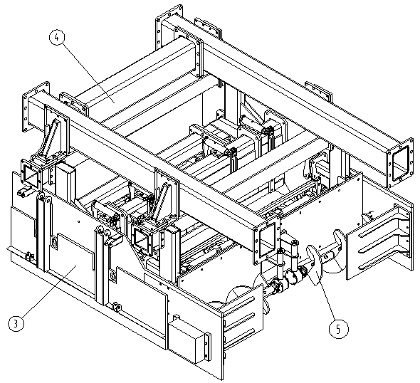
[0031] Such as figure 1 As shown in -14, the slip form paver with a rear mold mechanism includes a main machine 2, and a rear mold assembly 1 is connected to the rear side of the main machine 2, and the rear mold assembly 1 includes a rear frame 4 and a spiral material distribution device 5. Material level control device 6, vibrating device 7, vibrating device 8, forming mold 9, two sets of side template devices 3. The rear frame 4 is connected to the host machine 2, and the screw material distribution device 5, the material level control device 6, the vibrating device 7, the vibrating device 8, and the molding die 9 are sequentially arranged under the rear frame 4 from front to back.

[0032] Rear frame 4 comprises upper frame 22, front beam 23 and rear beam 21, the front end of upper frame 22 is connected with main frame 2, and front beam 23 and rear beam 21 are all connected with upper frame 22, the length of front beam 23 and rear beam 21 The directions are consistent wit...


PUM


Abstract

The invention discloses a slide mold paver provided with a postposed mold mechanism, relating to the field of rod construction. The slide mold paver comprises a main machine, wherein a postposed moldassembly is connected to the back side of the main machine and comprises a postposed framework, a spiral distributing device, a material level control device, a rapping device, a vibrating device, a forming mold and two side mold plate devices; the postposed framework is connected to the main machine, the spiral distributing device, the material level control device, the rapping device, the vibrating device and the forming mold are successively arranged below the postposed framework front and back, the material level control device is connected to the postposed framework, the spiral distributing device and the rapping device are connected to the material level control device, the forming mold is connected to the postposed framework, the rapping device is connected to the forming mold, andthe two side mold plate devices are separately connected to the left and right sides of the forming mold. The working width of the postposed mold assembly cannot be limited by the width of a tractiondevice of the main machine, and can be wider than the traction device of the main machine and also can be not wider than the traction device of the main machine.

Description

technical field [0001] The invention relates to the field of road construction, in particular to a mold mechanism for paving cement concrete road surfaces. Background technique [0002] Slipform paver usually adopts middle-mounted mold when paving the road surface, because of its balanced force and good paving effect, it is widely used. However, during the paving process, the travel drive device is located on the outside of the pre-paved road surface, and a space (usually occupying a width of about 0.5 to 1 meter) must be reserved at the edge of the pre-paved road for crawler walking. For rural roads and country roads and other road surface projects without soil shoulders, it is necessary to manually repair the space occupied by crawler belts, which affects the construction quality and consumes a lot of manpower. It restricts the application of slipform paver in small pavement engineering. Contents of the invention [0003] The purpose of the present invention is to over...

Claims


Application Information

Patent Timeline
Patent Type & Authority Applications(China)
IPC IPC(8): E01C19/48
CPCE01C19/4893
Inventor 赵国普黄烨蔡峰陆晨张艳徐宝国于勤玲
Owner JIANGSU SIMING ENG MACHINERY
Why Eureka
Try Eureka