
High-resolution computed tomography using edge-on detectors with temporally offset depth-segments

A technology of time migration and tomography, which is applied to radiological diagnostic instruments, radiation measurement, radiation intensity measurement, etc., can solve the problem of detector space change, achieve the effect of preventing aliasing and saving original image data

Inactive Publication Date: 2018-08-03
PRISMATIC SENSORS
View PDF13 Cites 0 Cited by
  • Summary
  • Abstract
  • Description
  • Claims
  • Application Information

AI Technical Summary

Problems solved by technology

The disadvantage of the flying spot method for detectors on the edge is that if you change the alignment of the detector relative to the source by moving the source, the spatial response of the detector changes
Therefore, oversampling schemes that include spatial offsets between detector elements in different depth segments are impractical if anti-scatter modules that are folded over each other between detector modules are used

Method used


Image

  • High-resolution computed tomography using edge-on detectors with temporally offset depth-segments
  • High-resolution computed tomography using edge-on detectors with temporally offset depth-segments
  • High-resolution computed tomography using edge-on detectors with temporally offset depth-segments

Examples


Embodiment Construction

[0038] Throughout the drawings, the same reference numerals are used to designate similar or corresponding elements.

[0039] To gain a better understanding of the proposed technology, it is useful to start the description with a brief system overview and / or analyze technical issues.

[0040] According to the proposed technique, a time offset is introduced between the initial measurement cycles of the detector elements in different depth segments on the detector on the edge. Due to the continuous rotation of the gantry, the shift in time corresponds to a shift in the angular coordinates of the measurements from the different depth segments, resulting in a higher sampling frequency in the angular direction. The sampling frequency can actually be increased by the number of depth segments on the detector. Furthermore, this method also achieves a higher sampling rate in the axial direction if the gantry rotates in a helical mode, ie the detector elements take measurements in a he...


PUM


Abstract

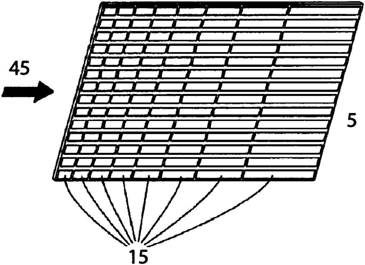
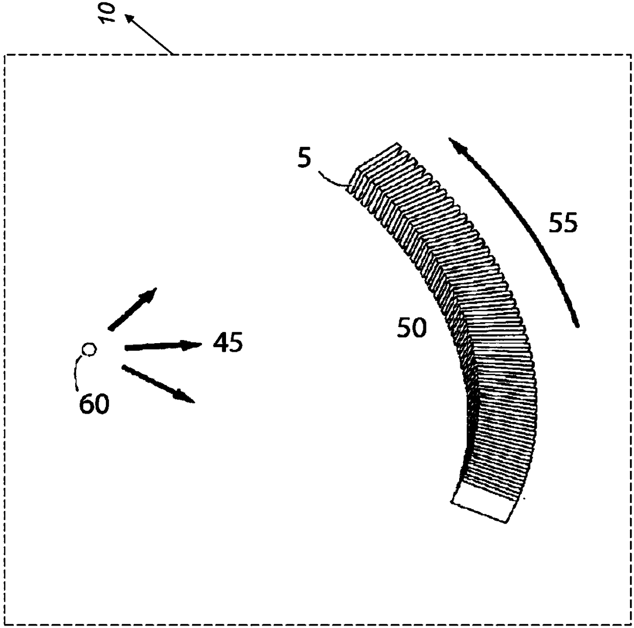
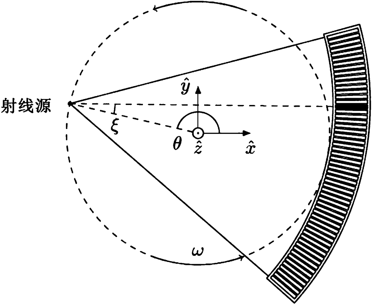
Disclosed is a measurement method performed by a Computed Tomography, CT, system (10). The CT system (10) comprises an x-ray source and an x-ray detector array of photon counting edge-on detectors, wherein each edge-on detector has a number of depth-segments, also referred to as detector elements (15), arranged at different spatial locations in the direction of incoming x-rays. The method comprises to apply a time offset measurement scheme that provides a time offset between measurement periods for at least two different detector elements (15) located at different depths, wherein the time offset is chosen so that at least two measurement periods at least partially overlaps in time. Disclosed is also a corresponding CT system (10), a control unit (20) for a CT system and a measurement circuit (30) for a CT system (10). A computer program controlling a CT system (10) is also disclosed. The disclosed technology provides for a higher sampling frequency in the angular direction.

Description

technical field [0001] The technique proposed by the present invention relates to a measurement method performed by a computed tomography system. The technique proposed by the present invention also relates to devices and systems configured to carry out the measurement method. Background technique [0002] Radiographic imaging, such as X-ray imaging, has been used in medical applications and non-destructive testing. [0003] Typically, an X-ray imaging system includes an X-ray source and an X-ray detector array comprising a plurality of detectors comprising one or more detector elements (independent devices that measure X-ray intensity / flux). An x-ray source emits x-rays which pass through the object or objects to be imaged and are then registered by the detector array. Since some materials absorb a greater portion of the x-rays than others, images are formed of objects or objects. [0004] An example of a commonly used X-ray imaging system is an X-ray computed tomography...

Claims


Application Information

Patent Timeline
Patent Type & Authority Applications(China)
IPC IPC(8): G01T1/24A61B6/03G01T1/29
CPCA61B6/4208G01T1/2985A61B6/032A61B6/54G01N23/046G01T1/24G01T1/29A61B6/4233A61B6/037A61B6/035A61B6/4241A61B6/03G01T1/247G01T1/242G01T1/17
Inventor 马丁·斯约林
Owner PRISMATIC SENSORS
Learn More