
Devices and systems for producing silicon

A technology of silicon dioxide, fused silicon, in the field of devices and systems for purifying silicon

Active Publication Date: 2018-08-03
MILWAUKEE SILICON LLC
View PDF2 Cites 3 Cited by
  • Summary
  • Abstract
  • Description
  • Claims
  • Application Information

AI Technical Summary

Problems solved by technology

The basic silicon volatile distillation and reduction model locks in the energy and capital costs that do not limit current relatively small-scale deployment of photovoltaic cells, but the energy cost of this established model precludes photovoltaic cells from being used as a solution for world energy shortages and global warming. The enormous scale of production required for a complete solution of the problem (where tens of terawatts of photovoltaic cells would need to be produced and would have to be produced in relatively few years)

Method used


Image

  • Devices and systems for producing silicon
  • Devices and systems for producing silicon
  • Devices and systems for producing silicon

Examples


Embodiment Construction

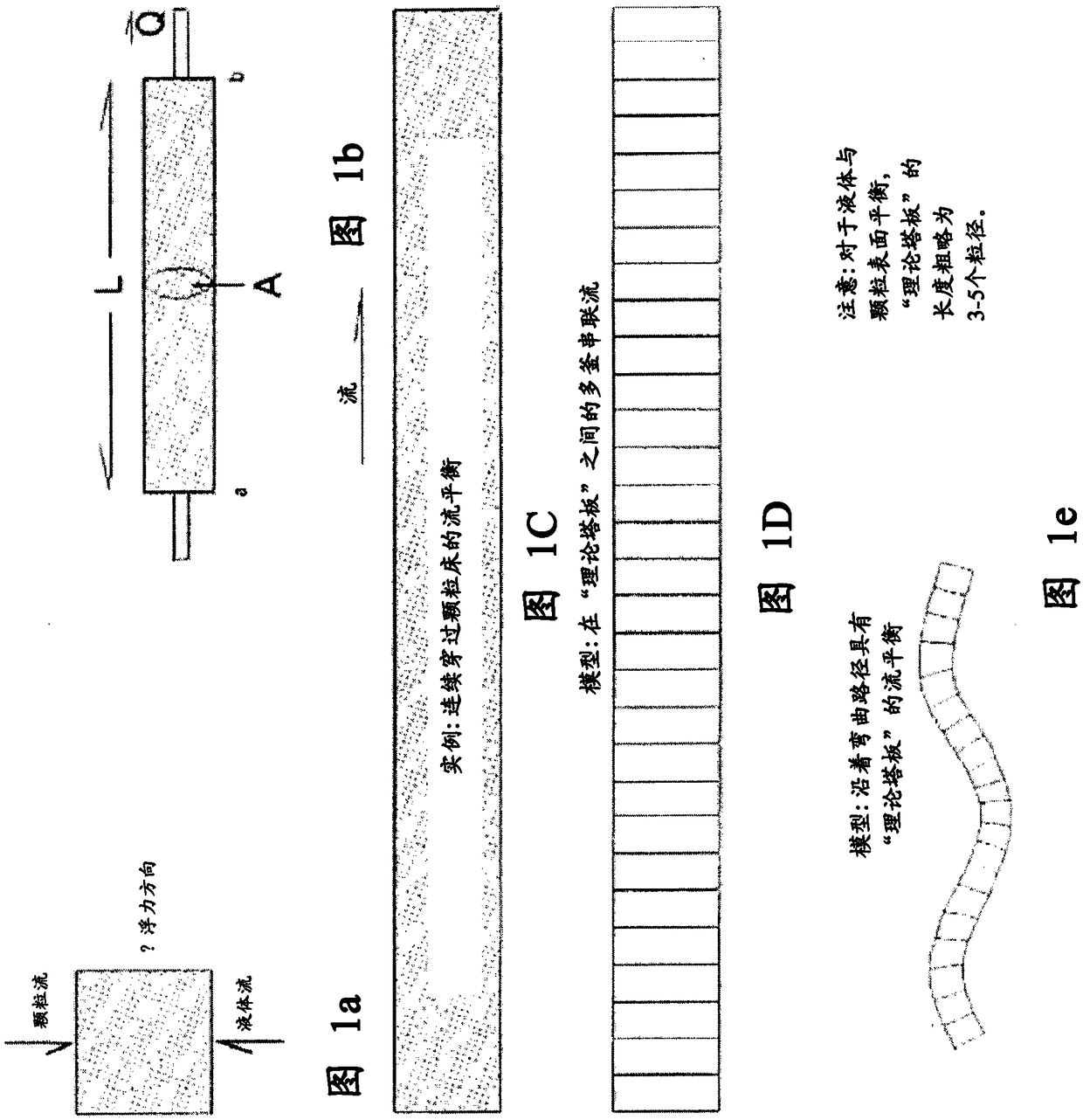
[0059] The present disclosure provides silica purification by a series of co-current and counter-current selective oxidative solvent exchanges over 1414°C. Some embodiments utilize Darcy flow structures similar to those used in packed bed and expanded bed column chromatography. Once the total silicon impurity concentration is low enough, complete purification for most or all impurity elements can be performed with an ordered expanded bed countercurrent purifier using thin-walled silica spheres formed in situ by oxygen bubbling as solvent particles, followed by argon This is accomplished by bubbling to remove dissolved oxygen (and possibly dissolved sulfur) from the molten silicon. The early stages of silica purification can be accomplished in a number of ways. Flowing molten silicon through a packed or expanded bed of silica particles effectively removes most of the impurity species. Selective oxidation of silicide and rapid diffusion of impurity elements through a packed or...


PUM


Abstract

The present disclosure provides devices and systems that utilize concurrent and countercurrent exchange platforms to produce purified silicon.

Description

Background technique [0001] The present disclosure is directed to apparatus and systems for producing purified silicon, and the purified silicon produced. [0002] Extreme purity is required in semiconductor silicon, and the best available silicon purity is very important in semiconductor production. Improved silicon purity translates into improved semiconductor production statistics as well as improved semiconductor operations. Silicon-based photovoltaic cell efficiency and photovoltaic cell production could also be more efficient if much purer silicon could be obtained cost-effectively for silicon-based photovoltaic cell production. In general, the ideal silicon (cost aside) for any photovoltaic or semiconductor purpose, considering ideal processing, is one of such high purity that elements other than silicon cannot be detected in the silicon, its purity So high that for any practical purpose the exact value of the impurity concentration is unimportant, and at the ideal li...

Claims


Application Information

Patent Timeline
IPC IPC(8): C01B33/037B01J8/24C01B23/00C10G11/18C30B11/00F27B14/06H01L31/18
CPCF27B14/06C01B33/037B01D15/02C30B11/00B01J2208/00893B01J2208/00752B01J2208/00548B01J10/005B01J8/20B01J8/1881C01P2006/80B01D21/0084B01J8/24B01J8/0278
Inventor R·M·肖沃尔特
Owner MILWAUKEE SILICON LLC
Learn More