
A terminal device and its manufacturing method

A terminal equipment, fingerprint collection technology, applied in branch equipment, equipment with sensors, instruments, etc., can solve the problems of limited placement of fingerprint modules, limited size of fingerprint modules, etc., to achieve maximum thinning. Effect

Active Publication Date: 2020-06-19
VIVO MOBILE COMM CO LTD
View PDF4 Cites 0 Cited by
  • Summary
  • Abstract
  • Description
  • Claims
  • Application Information

AI Technical Summary

Problems solved by technology

[0005] The purpose of the technical solution of the present invention is to provide a terminal device and its manufacturing method, which can solve the problem in the prior art that the placement of the fingerprint module is limited due to the limited size of the fingerprint module

Method used


Image

  • A terminal device and its manufacturing method
  • A terminal device and its manufacturing method
  • A terminal device and its manufacturing method

Examples


Embodiment Construction

[0022] In order to make the technical problems, technical solutions and advantages to be solved by the present invention clearer, the following will describe in detail with reference to the drawings and specific embodiments.

[0023] Aiming at the problem that the fingerprint module is designed separately in the prior art, and the size of the fingerprint module is limited, resulting in the problem that the location of the fingerprint recognition module is limited, the embodiment of the present invention provides a terminal device and its manufacturing method, which can make The setting position of the fingerprint recognition component is not limited.

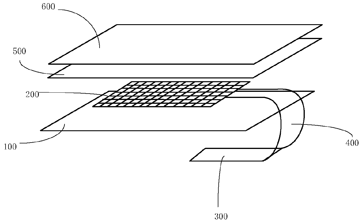
[0024] Figure 3 to Figure 6 Shown is a schematic structural diagram of a terminal device provided in an embodiment of the present invention, in which only components such as a display screen and a fingerprint identification component are illustrated, and components such as a backlight module are not illustrated.

[0025] Such ...


PUM


Abstract

The present invention provides a terminal device and a manufacturing method thereof. The terminal device provided by the present invention includes a display module and a fingerprint recognition component. The fingerprint recognition component includes: a fingerprint collection layer, and the fingerprint collection layer is attached to the display module. The set is used to collect fingerprint information; the fingerprint identification module is used to identify the collected fingerprint information; and, the flexible circuit board, the flexible circuit board is drawn from one side edge of the fingerprint collection layer, and is connected with the fingerprint collection layer. The above fingerprint recognition module connection. The terminal device and the manufacturing method thereof provided by the present invention can solve the problem in the prior art that the placement position of the fingerprint module is limited due to the size limitation of the fingerprint module.

Description

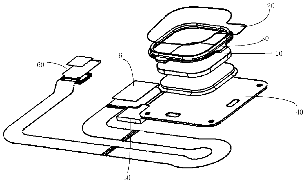
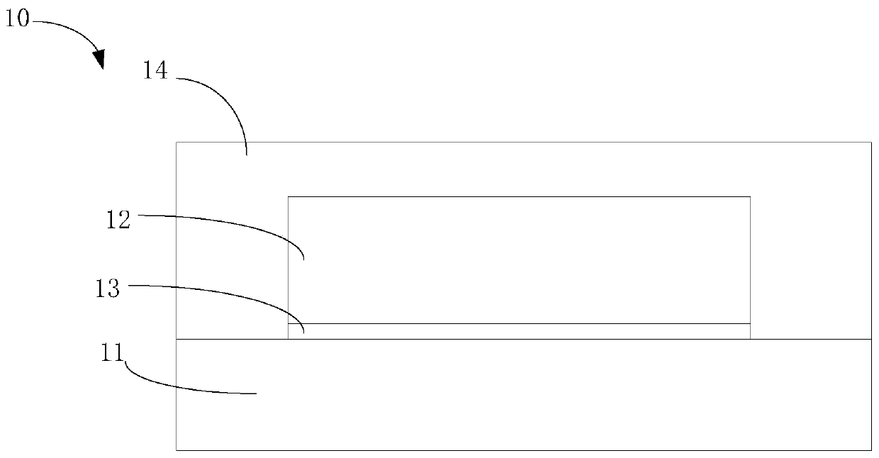
technical field [0001] The present invention relates to the technical field of terminal equipment, in particular to a terminal equipment and a manufacturing method thereof. Background technique [0002] figure 1 Shown is a schematic diagram of the assembly structure of the fingerprint module on the mobile phone in the prior art. Such as figure 1 As shown, the fingerprint module on the mobile phone in the prior art is an independent design, mainly including a fingerprint chip package 10, a protective film 20, a metal ring 30, an FPC (flexible circuit board) 40, components 50 and a connector 60, etc., Among them, such as figure 2 As shown, the fingerprint chip package 10 mainly includes a substrate 11, a fingerprint chip die 12 disposed on the substrate 11, a connection layer (DAF) 13 connected between the substrate 11 and the fingerprint chip die 12, and The encapsulation layer 14 and the fingerprint chip die are provided with a fingerprint collection structure (Sensor p...

Claims


Application Information

Patent Timeline
Patent Type & Authority Patents(China)
IPC IPC(8): G06K9/00H04M1/02G06V40/13
CPCH04M1/026H04M1/0266G06V40/1324G06V40/1306H04M2250/12G06V40/13G06V40/1329
Inventor 王建峰
Owner VIVO MOBILE COMM CO LTD
Learn More