Multi-channel inverter systems

An inverter and channel technology, applied in the field of multi-channel inverter systems, can solve problems such as imperfect coupling and achieve low total harmonic distortion and high efficiency

Active Publication Date: 2018-07-31
HUAWEI DIGITAL POWER TECH CO LTD
View PDF5 Cites 2 Cited by
  • Summary
  • Abstract
  • Description
  • Claims
  • Application Information

AI Technical Summary

Problems solved by technology

But the coupling between the two windings of a coupled inductor is not perfect
There may be a leakage path between the winding and the surrounding medium with low permeability

Method used


Image

  • Multi-channel inverter systems
  • Multi-channel inverter systems
  • Multi-channel inverter systems

Examples


Embodiment Construction

[0023] The making and using of the presently preferred embodiments are discussed in detail below. It should be appreciated, however, that the present invention provides many applicable inventive concepts that can be embodied in a wide variety of specific contexts. The specific embodiments discussed are merely illustrative of specific ways to make and use the invention, and do not limit the scope of the invention.

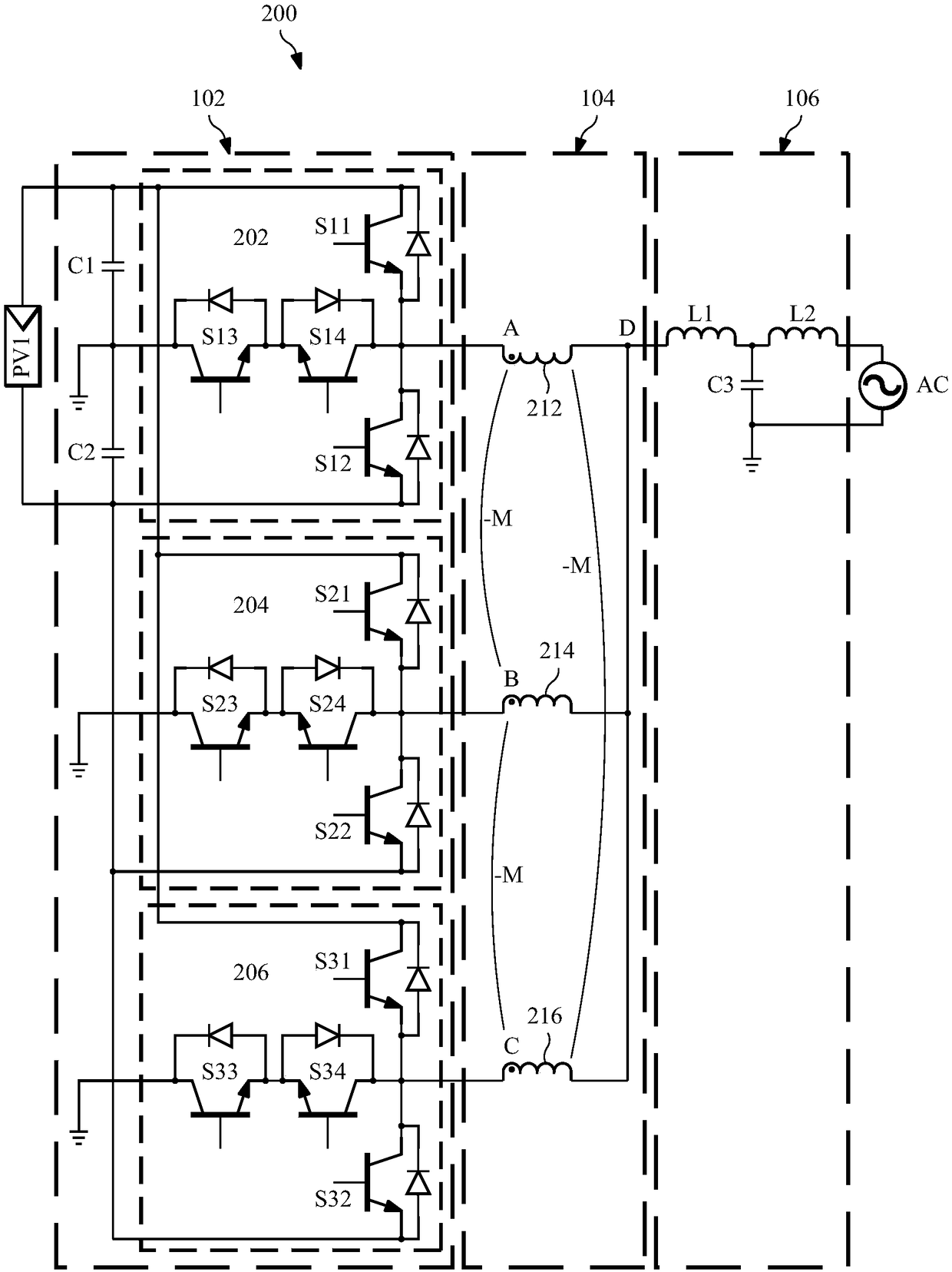
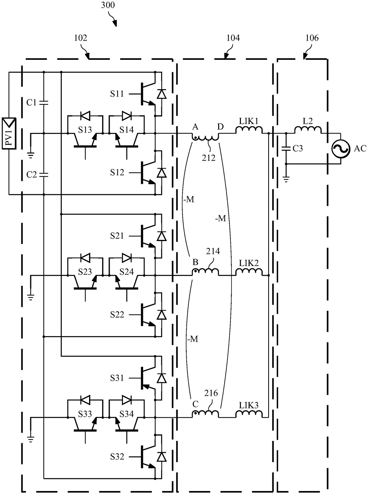
[0024] The invention will be described with reference to preferred embodiments in the specific context, namely a coupled inductor structure for connecting multiple inverter units of phases of a dc / ac power system. Additionally, coupled inductor structures can be used to connect the three phases of a dc / ac power system. However, the present invention can also be applied to various dc / ac power systems. Various embodiments will be described in detail below in conjunction with the accompanying drawings.

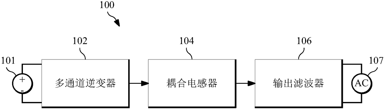
[0025] figure 1 A block diagram of a multi-channel inverter s...


PUM


Abstract

A system comprises a first T-type inverter connected to a dc power source, a second T-type inverter connected to the dc power source, wherein the second T-type inverter is configured to operate with afirst phase shift from the first T-type inverter, a third T-type inverter connected to the dc power source, wherein the third T-type inverter is configured to operate with a second phase shift from the second T-type inverter, a coupled inductor having a first input, a second input and a third input connected to the first T-type inverter, the second T-type inverter and the third T-type inverter respectively and an output filter coupled to the output of the coupled inductor.

Description

[0001] This application for patent claims priority to prior application to U.S. Patent Application Serial No. 14 / 933,723, filed November 5, 2015, entitled "Multi-Channel Inverter Systems," which earlier The entire content of the application is incorporated herein by reference. technical field [0002] The present invention relates to a device, system and method for load balancing among a plurality of parallel inverter units, and in a specific embodiment, relates to an Apparatus, system and method for implementing load balancing through coupled inductors between inductors. Background technique [0003] Renewable energy includes solar energy, wind energy, tidal energy, etc. A solar energy conversion system may include multiple solar panels connected in series or in parallel. The output of the solar panel generates a variable dc voltage based on various factors such as time of day, location, and sun-tracking capabilities. To regulate the output of the solar panel, the output...

Claims


Application Information

Patent Timeline
Patent Type & Authority Applications(China)
IPC IPC(8): H02M7/483
CPCH02M7/487H02M7/49H02M1/0064Y02B70/10H02M7/537H02M7/4815
Inventor 傅电波刘云峰
Owner HUAWEI DIGITAL POWER TECH CO LTD
Why Eureka
Try Eureka