Integrated brake cable tightness adjusting device

A technology for adjusting the tension and braking wire, which is applied to hand-held tools, appliances for tensioning wires, and manufacturing tools. Solve the effect of inconvenient operation

Inactive Publication Date: 2018-07-31
NANNING SHENGRUN TECH
View PDF9 Cites 1 Cited by
  • Summary
  • Abstract
  • Description
  • Claims
  • Application Information

AI Technical Summary

Problems solved by technology

[0002] There are brake lines in the brakes of electric vehicles, motorcycles, and bicycles. Some of the screws at the end of the brake lines are provided with threads, and some are only internal lines. After using the brakes for a period of time, as the brake pads wear out, you will find that the brakes are not as good as before. Sensitive, so adjust the screw at the end of the brake line to reduce the stroke of the brake handle. When adjusting the screw at the end of the brake line, the maintenance personnel will use their feet to push the brake rocker arm, and then hold the pliers with the left hand to clamp the end of the brake caliper backwards. Pull, and then use your right hand or other tools to turn the nut at the end of the brake line to adjust the stroke of the brake handle; the above operation steps are cumbersome, and when pulling the brake line, a relatively large force is required. When adjusting the brake line, it is easy to hurt the hand turning the screw at the end of the brake line, and it is necessary to use a wrench to adjust the screw on the brake line while adjusting the brake line. The existing wrench cannot be fixed on the brake line tightness adjustment device, so the operation is inconvenient

Method used


Image

  • Integrated brake cable tightness adjusting device
  • Integrated brake cable tightness adjusting device
  • Integrated brake cable tightness adjusting device

Examples


Embodiment Construction

[0026] The preferred embodiments of the present invention will be described in detail below in conjunction with the accompanying drawings: It should be understood that the preferred embodiments are only for illustrating the present invention, rather than limiting the protection scope of the present invention.

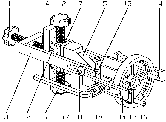
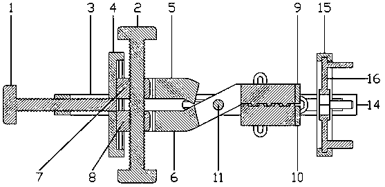
[0027] Such as Figures 1 to 9As shown, an integrated brake line tightness adjustment device includes an upper pressing rod 5 and a lower pressing rod 6. The middle part of the upper pressing rod 5 and the middle part of the lower pressing rod 6 are intersected and connected, and the intersection is installed with a second A mother and son rivet 11, the intersection of the upper pressing rod 5 and the lower pressing rod 6 is equipped with a support frame 3 through the first mother and son rivet 11, and an upper movable block 7 is installed in the upper pressing rod 5, A lower movable block 8 is installed in the lower pressing rod 6, a support plate 4 is installed betwee...


PUM


Abstract

The invention relates to an integrated brake cable tightness adjusting device and belongs to the technical field of electric vehicle maintenance. The integrated brake cable tightness adjusting devicecomprises a screw loosening and tightening device, an upper pressing rod and a lower pressing rod. The middle of the upper pressing rod and the middle of the lower pressing rod are connected in a crossed mode, and a supporting frame is mounted on the crossed position of the upper pressing rod and the lower pressing rod. An upper movable block is mounted in the upper pressing rod, and a lower movable block is mounted in the lower pressing rod. A supporting plate is mounted between the upper movable block and the lower movable block, and a first screw is arranged between the supporting plate andthe tail of the supporting frame. A lower jacking plate is mounted in the upper pressing rod, and an upper jacking plate is mounted in the lower pressing rod. The upper jacking plate and the lower jacking plate are both connected with the supporting frame. According to the integrated brake cable tightness adjusting device, the tail of a brake cable is clamped through a clamping plate; then through sliding of the jacking plates, a brake rocker arm is pushed out, the brake cable is pulled out, and thus the effects that brake adjusting is convenient and saves labor are achieved; and the situation that when the brake cable or the brake rocker arm breaks away, hands of an operator are scratched can further be prevented.

Description

technical field [0001] The invention relates to a device for adjusting the tightness of an integrated brake line, which belongs to the technical field of electric vehicle maintenance. Background technique [0002] There are brake lines in the brakes of electric vehicles, motorcycles, and bicycles. Some of the screws at the end of the brake lines are provided with threads, and some are only internal lines. After using the brakes for a period of time, as the brake pads wear out, you will find that the brakes are not as good as before. Sensitive, so adjust the screw at the end of the brake line to reduce the stroke of the brake handle. When adjusting the screw at the end of the brake line, the maintenance personnel will use their feet to push the brake rocker arm, and then hold the pliers with the left hand to clamp the end of the brake caliper backwards. Pull, and then use your right hand or other tools to turn the nut at the end of the brake line to adjust the stroke of the b...

Claims


Application Information

Patent Timeline
IPC IPC(8): B25B25/00B25B27/14
CPCB25B25/00B25B27/0035B25B27/0071B25B27/143
Inventor 姚清脐符绩承
Owner NANNING SHENGRUN TECH
Why Eureka
Try Eureka