
Multi-groove pot used for tea making and tea making method thereof

A technology for multi-slot pots and tea, which is applied in tea treatment before extraction, etc. It can solve the problems of tea bending, affecting the service life of equipment, and poor tidying effect, etc.

Pending Publication Date: 2018-07-31
程水良
View PDF1 Cites 0 Cited by
  • Summary
  • Abstract
  • Description
  • Claims
  • Application Information

AI Technical Summary

Problems solved by technology

[0003] In order to improve the tea efficiency and the output of tea, the existing multi-groove pot usually adopts an integral U-shaped groove plate to realize the effect of tea organization through the U-shaped groove plate; however, the integral U-shaped groove plate exists There are the following defects: the length of the integral U-shaped groove plate is relatively long, and the U-shaped groove plate will be bent during the long-term processing process, so there is a shortcoming of the U-shaped groove plate having a low service life
[0005] Although the above-mentioned technical scheme can solve the technical problem of "the U-shaped groove plate will be bent during the long-time straightening process", the multi-slot pot provided by the technical scheme is relatively single for the tealeaves, that is, the tealeaves are in the In the process of transmission in the U-shaped trough, it can only be arranged on the front and rear U-shaped troughs on the same straight line, and because the groove widths of the front and rear U-shaped troughs on the same straight line are uniform, when the U-shaped trough appears When there are less tea leaves in a certain place, the tea leaves will be seriously bent during the process of straightening, so there is a shortcoming of poor straightening effect; Clamped in the gap between the split pots, first, it will cause waste and loss of tea leaves, and second, if the tea leaves are in the gap for a long time, the gap between the split pots will expand, which will affect the service life of the equipment

Method used


Image

  • Multi-groove pot used for tea making and tea making method thereof
  • Multi-groove pot used for tea making and tea making method thereof
  • Multi-groove pot used for tea making and tea making method thereof

Examples


Embodiment 1

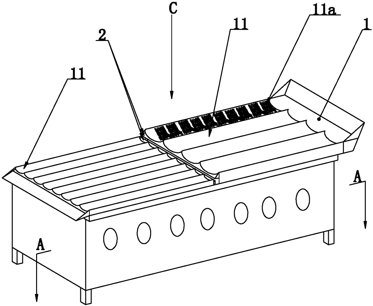
[0038] Such as Figure 1 ~ Figure 4 As shown, the present invention discloses a multi-slot pot for making tea. In a specific embodiment of the present invention, more than two independent U-shaped pot bodies 1 are arranged at intervals along the length direction; each independent U-shaped pot body 1 is arranged along the The length direction is arranged in a ladder shape, and a feeding assembly 2 for transporting tea from the front independent U-shaped pot 1 to the rear independent U-shaped pot 1 is provided between adjacent independent U-shaped pots 1 .

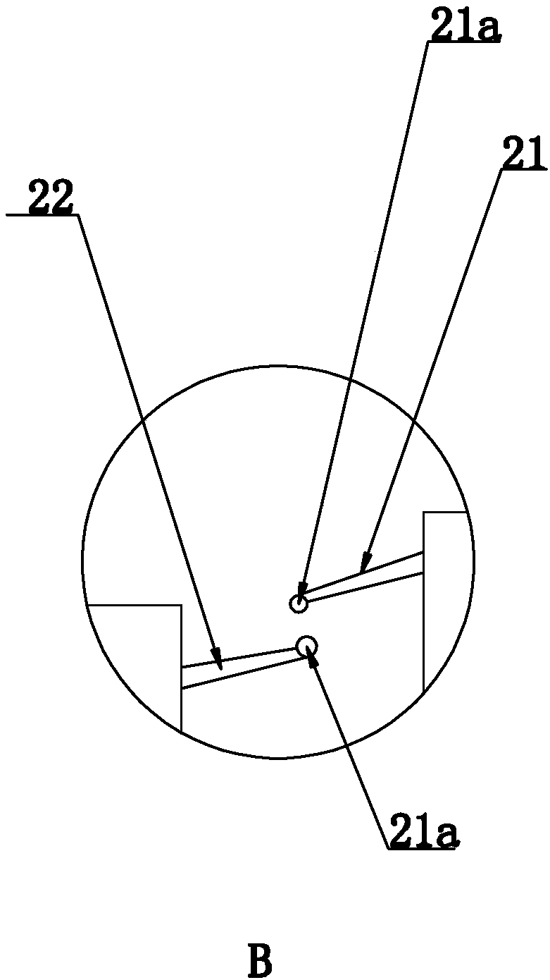
[0039] In a specific embodiment of the present invention, the material transfer assembly 2 includes a transfer plate 21 fixed at the discharge port of the front independent U-shaped pot 1 and a receiving plate 22 fixed at the feed port of the rear independent U-shaped pot 1 , the transfer plate 21 is located above the feed inlet of the receiving plate 22, and the transfer plate 21 and the receiving plate 22 partially overlap...

Embodiment 2

[0051] Embodiment 2, the difference with embodiment 1 is

[0052] Such as Figure 5 As shown, in a specific embodiment of the present invention, the groove width L1 of the U-shaped groove plate 11 constituting the front U-shaped pot body 1 may be smaller than the groove width L2 of the U-shaped groove plate 11 constituting the rear U-shaped pot body 1 .

[0053] By adopting the above-mentioned technical scheme: since there are many kinds of tea leaves, this technical means can be adopted when dealing with some tea leaves with large leaf area, that is, the groove width of the U-shaped groove plate of the front U-shaped pot body is smaller than that of the rear U-shaped pot. The setting of the groove width of the U-shaped groove plate of the shaped pot body; the beneficial effect of this setting is: when the tea leaves enter the U-shaped groove plate with a wider groove width from the U-shaped groove plate with a narrower groove width, it can effectively Improve the air permeab...

Embodiment 3

[0054] Embodiment 3, the difference with embodiment 1 is

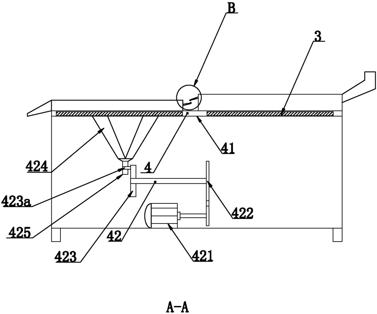
[0055] Such as Figure 6 As shown, in the specific embodiment of the present invention, the bottom of each independent U-shaped pot body 1 is provided with a driving assembly 4 that respectively drives each independent U-shaped pot body 1 to reciprocate and swing.

[0056] By adopting the above technical scheme, different driving components drive different independent U-shaped pots to move, which can increase the rolling range of tea leaves, improve the efficiency of tea drying, make tea leaves easier to shape, and further improve the quality of the tea leaves. Effect.


PUM


Abstract

The present invention discloses a multi-groove pot used for tea making. The multi-groove pot is characterized in that: the multi-groove pot comprises two or more independent U-shaped pot bodies arranged at intervals along a length direction; each independent U-shaped pot body is arranged in a stepwise manner along the length direction; besides, a material transporting assembly for transporting tealeaves from the front independent U-shaped pot body to the rear independent U-shaped pot body is arranged between the adjacent independent U-shaped pot bodies; the material transporting assembly comprises a transfer plate fixed at the material outlet place of the front independent U-shaped pot body and a receiving plate fixed at the material inlet of the rear independent U-shaped body; the transfer plate is located above the material inlet of the receiving plate; and besides, the transfer plate and the receiving plate are partially overlapped in a height direction. The tea making method is characterized by comprising the following steps: S1, material feeding; S2, heating and enzyme-deactivating; S3, transiting and mixing; and S4, final shaping. Beneficial effects are as follows: the multi-groove pot is improved in diversification and effects of tea strip tidying, and improves quality of the tea leaves.

Description

technical field [0001] The invention relates to the technical field of tea-making equipment, in particular to a tea-making multi-slot pot and a tea-making method thereof. Background technique [0002] The multi-slot pot refers to a kind of equipment for baking and sorting tea leaves. [0003] In order to improve the tea efficiency and the output of tea, the existing multi-groove pot usually adopts an integral U-shaped groove plate to realize the effect of tea organization through the U-shaped groove plate; however, the integral U-shaped groove plate exists There are following defects: the length of the integral U-shaped groove plate is longer, and the U-shaped groove plate will be bent in the long-term process of trimming, so there is a shortcoming of the U-shaped groove plate having a low service life. [0004] Aiming at the deficiencies of the prior art, the patent application publication number CN104255964A and the application publication date of January 7, 2015 disclose...

Claims


Application Information

Patent Timeline
Patent Type & Authority Applications(China)
IPC IPC(8): A23F3/06A23F3/12
CPCA23F3/06A23F3/12
Inventor 程水良
Owner 程水良
Learn More