
Electronic assembly

A technology for electronic components and display components, applied in electrical components, sensor parts, sensors, etc., to solve problems such as damage to the touch screen, affecting sound quality, and complex structure

Pending Publication Date: 2018-07-27
KINGTONE INNOVATION BEIJING TECH +1
View PDF1 Cites 4 Cited by
  • Summary
  • Abstract
  • Description
  • Claims
  • Application Information

AI Technical Summary

Problems solved by technology

During the working process, the driver directly pushes the screen to vibrate through the silicone pad. The touch screen is a precision component. If the silicone pad contacts the touch screen and transmits mechanical vibration energy during operation, the touch screen will be damaged.
At the same time, due to the large size of the piezoelectric driver, the screen must reserve an additional non-touch and non-display area for the driver
Therefore, this patent is no longer suitable for the technical requirements of current full-screen mobile phones, tablet computers and other devices; at the same time, the driver is large in size and relatively complex in structure. For some devices with thickness requirements, this patented technology cannot be used.
At the same time, when the piezoelectric driver is working, it only drives the two sides of the screen to vibrate locally. The other two sides of the screen and the central area of ​​the screen need to be driven by the rigidity of the screen itself. This structure will cause the frequency response curve to be uneven in the middle and high frequencies, which will affect the sound quality.
The piezoelectric driver in this patent is a strip-shaped piezoelectric sheet, which generates bending vibration when it is energized, and transmits it to the screen through the silicone pad to vibrate and produce sound. The vibration effect is weak, which in turn affects the sensitivity of the sounder

Method used


Image

  • Electronic assembly
  • Electronic assembly
  • Electronic assembly

Examples


Embodiment 1

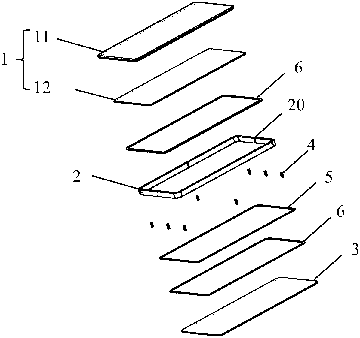
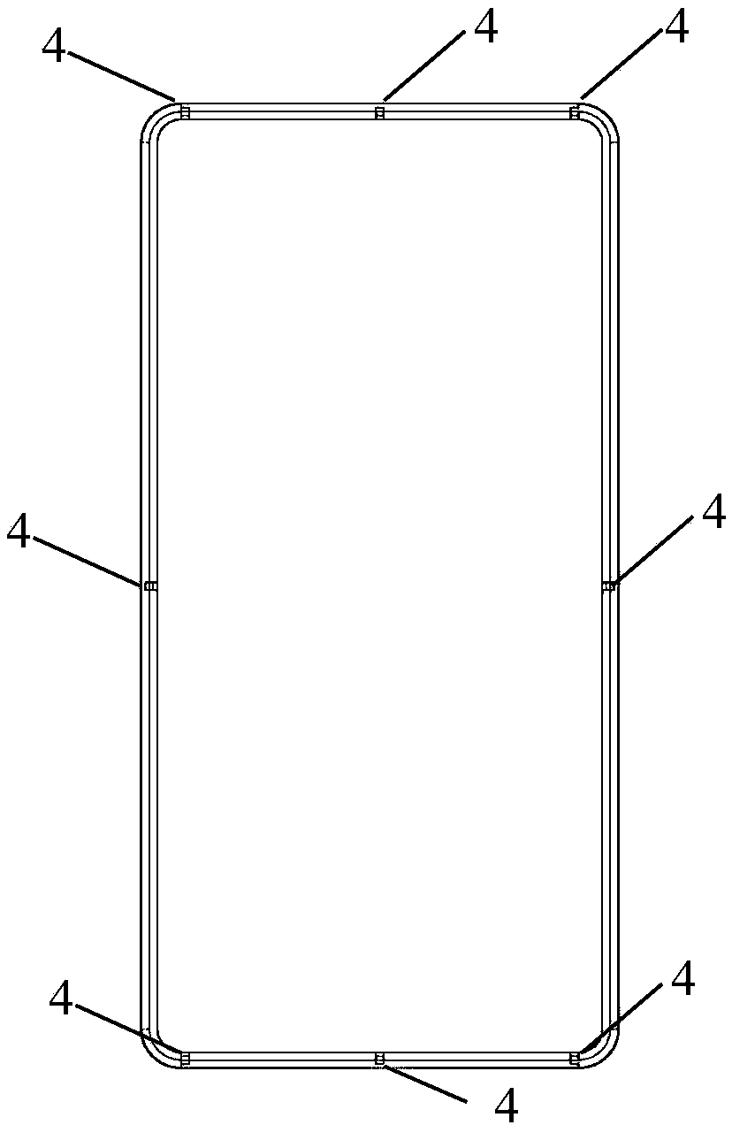
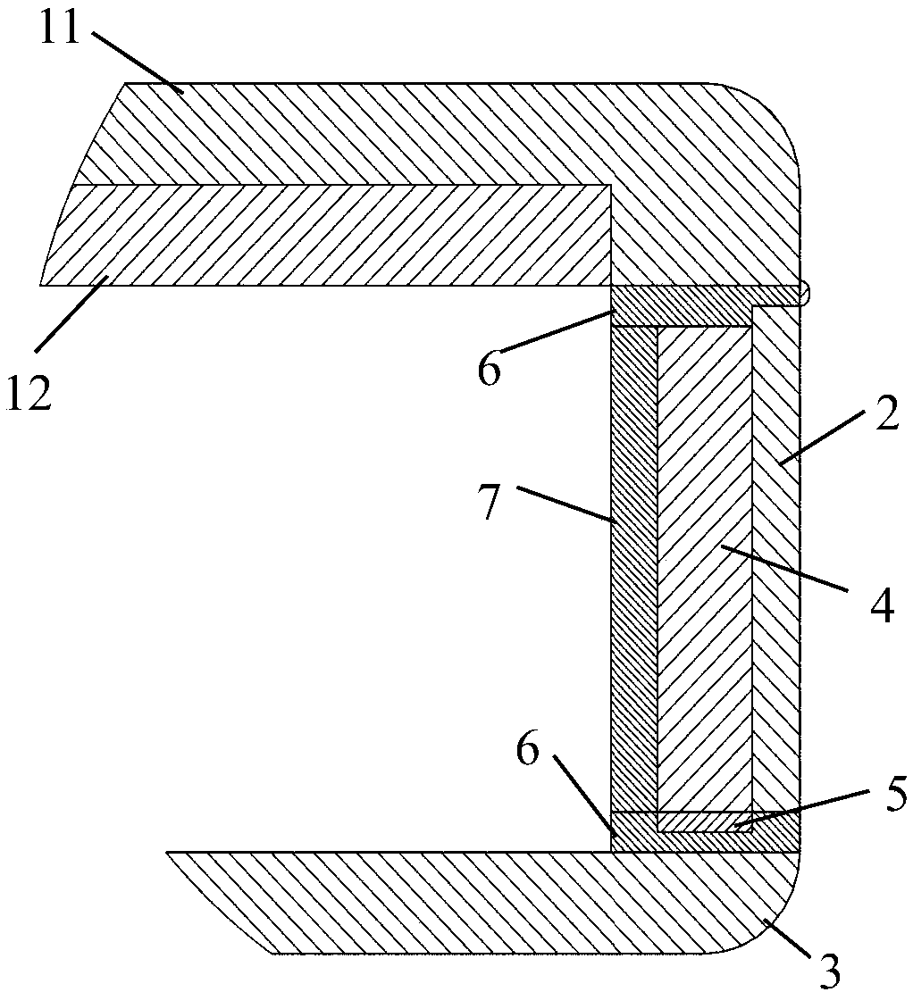
[0055] Figure 1-Figure 3 is a schematic diagram of the electronic assembly of this embodiment. Such as Figure 1-Figure 3 As shown, the electronic assembly includes a display screen assembly 1 , a side frame 2 , a rear case 3 , a piezoelectric transducer 4 and a flexible circuit board 5 . The display screen assembly 1 includes a transparent front case 11 and a display screen 12 . The length and width of the transparent front case 11 are larger than the length and width of the display screen 12, and the transparent front case 11 is provided with a groove opening downward, and the display screen 12 is arranged in the opening groove of the transparent front case 11, Fitted with the transparent front case 11, so that the display screen 12 coincides with the top of the opening groove, thereby reducing the overall thickness of the electronic components, such as image 3 shown. The material of the transparent front shell 11 is transparent glass, and the information displayed on ...

Embodiment 2

[0069] Figure 4 It is a partial cross-sectional schematic diagram of the electronic assembly of this embodiment. Such as Figure 4 As shown, the electronic assembly includes a transparent front case 11 , a display screen 12 , a side frame 2 , a rear case 3 , a piezoelectric transducer 4 and a flexible circuit board 5 . The structure of the electronic components in this embodiment is basically the same as in Embodiment 1, the only difference is that the bottom of the side frame 2 is provided with a vibration isolation structure, and when the piezoelectric transducer 4 is controlled to stretch and vibrate, the sealing layer 6 drives the display. The screen assembly 1 vibrates, but cannot drive the rear case 3 to vibrate together.

[0070] In this embodiment, the side frame 2 includes a first frame 21 and a second frame 22 . The first frame 21 is arranged on the outer side of the electronic component, and plays a role of support and protection. The second frame 22 is dispose...


PUM

PropertyMeasurementUnit
Cross section diameteraaaaaaaaaa
Heightaaaaaaaaaa
Side lengthaaaaaaaaaa

Abstract

The invention discloses an electronic assembly. The electronic assembly comprises a display screen assembly, a side frame, a back casing, a plurality of piezoelectric transducers and a flexible circuit board. The plurality of piezoelectric transducers are arranged in a groove of the side frame; and through electric connection of the flexible circuit board and the piezoelectric transducers, the piezoelectric transducers can mutually convert electric energy and mechanical energy, so that the electronic assembly can realize different functions. The electronic assembly is simple in structure, canreplace the traditional loudspeaker or telephone receiver which is arranged on multimedia equipment, and can improve the sensitivity and the tone quality of the loudspeaker. Meanwhile, the piezoelectric transducers can be arranged on an edge of the display screen, so that a full screen can be matched and the application range of the piezoelectric transducers can be increased.

Description

technical field [0001] The invention relates to the field of multimedia electronic devices, in particular to an electronic component. Background technique [0002] With the continuous development of the mobile Internet, smart mobile devices have become an indispensable item in life. The communication and other voice functions of smart mobile devices are one of the necessary conditions, so the speakers in smart mobile devices are very important. Patent CN102917299B proposes a screen sounder, including a screen and a driver. The screen sounder is provided with a driver under the screen, and the vibration of the driver can make the screen vibrate and emit sound. [0003] The driver in this patent is long and must be arranged on the two parallel sides of the screen, with a certain distance from the touch screen. The driver directly pushes the screen to vibrate through the silicone pad during operation. The touch screen is a precision component. If the silicone pad contacts th...

Claims


Application Information

Patent Timeline
IPC IPC(8): H04R23/00
CPCH04R23/006
Inventor 袁世明袁子姜开利范守善周铁英闫鑫
Owner KINGTONE INNOVATION BEIJING TECH
Learn More