Method for predicting deformation of additive manufacturing part

A technology for additive manufacturing and parts, applied in the field of predicting the deformation of additive manufacturing parts, it can solve the problems of large-scale calculation and low efficiency of large and medium-sized parts in additive manufacturing, which can reduce the calculation time, simplify the calculation process, and improve the The effect of efficiency

Active Publication Date: 2018-07-27
TSINGHUA UNIV
View PDF6 Cites 10 Cited by
  • Summary
  • Abstract
  • Description
  • Claims
  • Application Information

AI Technical Summary

Problems solved by technology

However, research on the prediction and control of stress and deformation of parts in laser additive manufacturing is still in its infancy at home and abroad.
Due to the complex factors of additive manufacturing, the modeling and calculation of the additive process has become a very challenging task
[0004] In recent years, some scholars have used the traditional finite element numerical simulation method to study the influence of process parameters on deformation during the additive process. The common practice is to use the moving heat source method to obtain the additive manufacturing temperature field, and then use the additive manufacturing temperature field as The form of the predefined field is imported into the calculation of the stress / strain field of the part. This finite element numerical simulation method is inefficient and suitable for the simulation of smaller test parts
[0005] As the size of parts that need to be simulated in the metal additive manufacturing process becomes larger and larger, when the traditional finite element numerical simulation method is used for simulation calculation, due to the increasing number of finite element meshes, the numerical simulation time has exceeded the tolerable Therefore, the traditional finite element numerical simulation method has been difficult to achieve large-scale calculation of large parts in additive manufacturing

Method used


Image

  • Method for predicting deformation of additive manufacturing part
  • Method for predicting deformation of additive manufacturing part
  • Method for predicting deformation of additive manufacturing part

Examples


Embodiment Construction

[0026] The method for predicting deformation of additively manufactured parts according to the present invention will be described in detail below with reference to the accompanying drawings.

[0027] refer to Figure 1 to Figure 3 , the method for predicting the deformation of additively manufactured parts according to the present invention includes steps: S1, S2, S3 and S4.

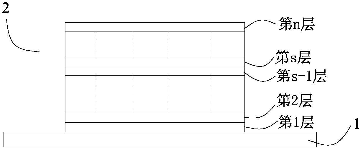
[0028] S1, establish a three-dimensional solid model 1 of a pre-printed part formed by stacking n-layer metal units on the substrate 2 (such as figure 1 shown), wherein the first layer metal unit is the lowermost metal unit of the three-dimensional solid model 1 of the pre-printed part, the n-th layer metal unit is the uppermost metal unit of the three-dimensional solid model 1 of the pre-printed part, and the pre-printed The length direction of the three-dimensional solid model 1 of the part is the x direction, the width direction is the y direction, the height direction is the z direction, and the ce...


PUM


Abstract

The invention provides a method for predicting deformation of an additive manufacturing part. According to the method, a three-dimensional solid model of a preprinted part is established according tocharacteristics and technological characteristics of additive manufacturing and is subjected to heat transfer analysis according to actual printing paths, then corresponding distribution functions ofthe temperature in time and space are constructed by an additive manufacturing temperature field when a moving heat source activates each layer of metal units in the heat transfer analysis by data fitting software, and the corresponding distribution functions in mechanical analysis are used as thermal boundary conditions for activating each layer of metal units. Thus, not only can the calculationprocess of mechanical analysis be simplified, but also accuracy of mechanical analysis results can be effectively ensured, and efficiency of deformation prediction of the additive manufacturing part is greatly improved. Compared with a traditional finite element numerical simulation method, the method has the advantages that calculation time is shortened by 90% or higher and calculation efficiencyis improved by 10 times, and the method is suitable for large-scale calculation of large parts in additive manufacturing.

Description

technical field [0001] The invention relates to the technical field of additive manufacturing, in particular to a method for predicting deformation of additively manufactured parts. Background technique [0002] As a strategic emerging industry, additive manufacturing technology is highly valued and actively promoted by all countries. At present, metal additive manufacturing is mainly used for large and complex parts that are difficult to prepare by traditional methods. However, a key technical bottleneck faced by this technology is the problem of part deformation, which will greatly affect the precision and size of the part or even crack, making the part unusable. [0003] In order to reduce the deviation between the formed part and the preset model as much as possible and avoid measures such as subsequent machining and thermal correction deformation, it is necessary to use numerical simulation to predict the deformation of the part before printing the part and reduce the ...

Claims


Application Information

Patent Timeline
Patent Type & Authority Applications(China)
IPC IPC(8): G06F17/50B33Y50/00
CPCB33Y50/00G06F30/17G06F30/23
Inventor 史清宇谢瑞山陈高强吴建军赵玥
Owner TSINGHUA UNIV
Why Eureka
Try Eureka