
Wall slotting device for power wiring

A technology for power wiring and walls, which is applied in the field of wall slotting devices for power wiring, and can solve problems such as affecting the appearance, easy to cut and crooked, labor-intensive and time-consuming, etc.

Active Publication Date: 2018-07-27
海安美物菲斯物联网科技有限公司
View PDF11 Cites 1 Cited by
  • Summary
  • Abstract
  • Description
  • Claims
  • Application Information

AI Technical Summary

Problems solved by technology

[0002] Power wiring is an extremely labor-intensive and time-consuming task whether it is for factory installation equipment or residential decoration. Power wiring needs to dig grooves of corresponding width and depth on the building. Because the building wall is relatively hard, it is difficult to dig deep. , and the length of wiring required is large, which brings great difficulty to manually digging grooves, wastes a lot of time, and seriously affects the overall work progress
[0003] At present, some wall excavation devices for power wiring on the market have only one cutter, and two cutting operations need to be performed manually. In some uneven places, it is easy to cut crookedly, which affects the appearance. After cutting, use an electric hammer Although manual excavation of the wall is much more convenient than pure handwork, it is far from meeting people's requirements for economic benefits. Moreover, when working with an electric hammer, the wall will be broken through if you are not careful, wasting manpower and time.

Method used


Image

  • Wall slotting device for power wiring
  • Wall slotting device for power wiring
  • Wall slotting device for power wiring

Examples


Embodiment Construction

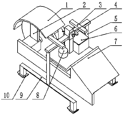
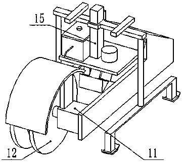
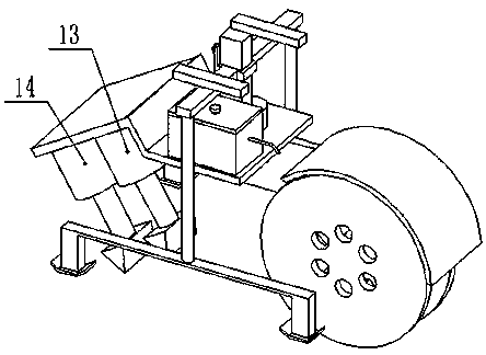
[0017] The present invention is realized through the following technical solutions: a wall slotting device for power wiring, including a dust-proof cover plate 1, a first bracket 2, a hand-held bracket 3, bolts 4, a second bracket 5, a water tank 6, and a third bracket 7. The controller 8, the fourth bracket 9, the slide plate 10, the motor 11, the cutter 12, the first electromagnet 13, the second electromagnet 14 and the fifth bracket 15, the dustproof cover 1 is arc-shaped, It is installed on the first bracket 2, and the first bracket 2 is fixed on the motor 11. There are two handheld brackets 3, which are respectively fixed on the upper ends of the two second brackets 5, so that workers can push the device forward. 4 is installed between two handheld brackets 3, and there are two second brackets 5, which are respectively installed in the middle of the two fourth brackets 9 on the left and right sides of the device, and the water tank 6 is installed on the third bracket 7, I...


PUM


Abstract

The invention discloses a wall slotting device for power wiring, and belongs to the field of building engineering equipment. Two handheld supports are arranged and are fixed to the upper ends of two second supports, a water tank is arranged on a third support, the position of the water tank is located below the handheld support on the right side, a controller is arranged on a third support, the position of the controller is located below the handheld support on the left side, an electric motor is arranged on the third support, cutters are in a disc shape, two cutters are arranged, a first electromagnet is arranged below the inclined part of the third support, the lower end of the first electromagnet is provided with a triangular hammer head, a second electromagnet is arranged behind the first electromagnet, and a fifth support is fixed to the third support. The electric motor drives the cutters to rotate to line out cutting lines on the wall, the controller controls the first electromagnet and the second electromagnet to move up and down for slotting the wall, labor force is saved, and work efficiency is improved.

Description

technical field [0001] The invention relates to a wall slotting device for power wiring, in particular a motor drives a cutter to rotate to draw a cutting line on the wall, and a controller controls the first electromagnet and the second electromagnet to move up and down A device for slotting a wall belongs to the field of construction engineering equipment. Background technique [0002] Power wiring is an extremely labor-intensive and time-consuming task whether it is for factory installation equipment or residential decoration. Power wiring needs to dig grooves of corresponding width and depth on the building. Because the building wall is relatively hard, it is difficult to dig deep. , and the length of the required wiring is large, which brings great difficulty to manually excavating the groove, wastes a lot of time, and seriously affects the overall work progress. [0003] At present, some wall digging devices for power wiring on the market have only one cutter, and two...

Claims


Application Information

Patent Timeline
Patent Type & Authority Applications(China)
IPC IPC(8): B28D1/00B28D7/02B28D7/00
CPCB28D1/003B28D7/00B28D7/02
Inventor 宁满林
Owner 海安美物菲斯物联网科技有限公司
Learn More