Fast clamping device for cylinder head and cylinder sleeve

A technology of clamping device and cylinder liner, which is applied in the field of quick clamping device of cylinder head and cylinder liner, can solve problems such as inaccurate positioning of cylinder liner, easy swing of cylinder liner, poor coaxiality of products, etc., and achieve good coaxiality , Avoid shaking and displacement, and the effect of high product quality

Inactive Publication Date: 2018-07-27
CHONGQING BORUN MOLD CO LTD
View PDF3 Cites 0 Cited by
  • Summary
  • Abstract
  • Description
  • Claims
  • Application Information

AI Technical Summary

Problems solved by technology

[0003] With the current development trend of the engine, the explosion pressure of the engine is getting higher and higher (the maximum explosion pressure of many existing engines has reached or exceeded 180MPa), if the connection between the cylinder liner and the cylinder head is unreliable, it will lead to engine failure. Air leakage or piston difficulty and other defects, so the cylinder liner requires high machining accuracy to ensure the stability of the work
[0004] However, in the die-casting production of the cylinder head, the traditional technology is to manually hold the cylinder liner and place it in the die-casting mold, and then enter the die-casting process of the cylinder head. During the die-casting process, the placed cylinder liner is not clamped and positioned. , the cylinder liner is prone to swing during die-casting processing, resulting in inaccurate positioning of the cylinder liner and out-of-tolerance coaxiality of processed products, etc.

Method used


Image

  • Fast clamping device for cylinder head and cylinder sleeve
  • Fast clamping device for cylinder head and cylinder sleeve
  • Fast clamping device for cylinder head and cylinder sleeve

Examples


Embodiment Construction

[0028] The specific implementation manner and working principle of the present invention will be further described in detail below in conjunction with the accompanying drawings.

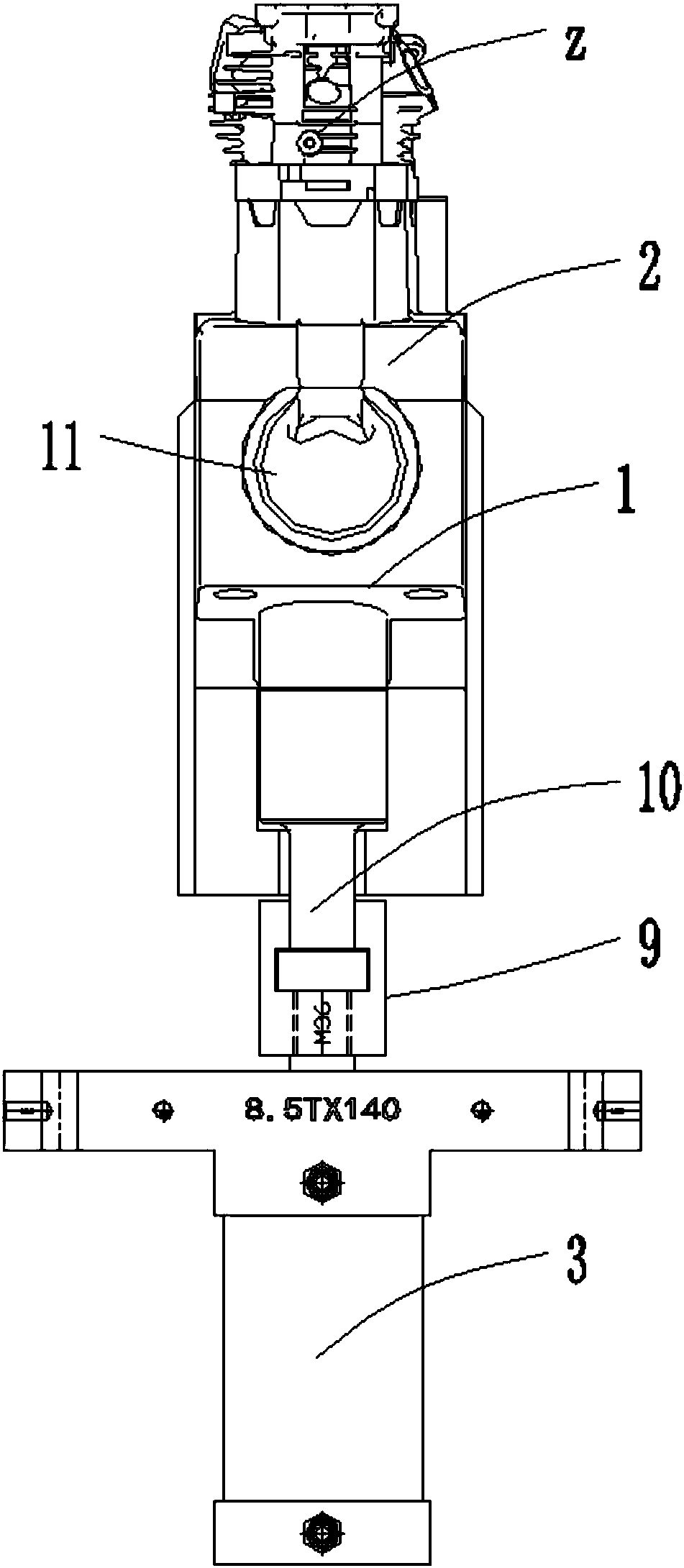
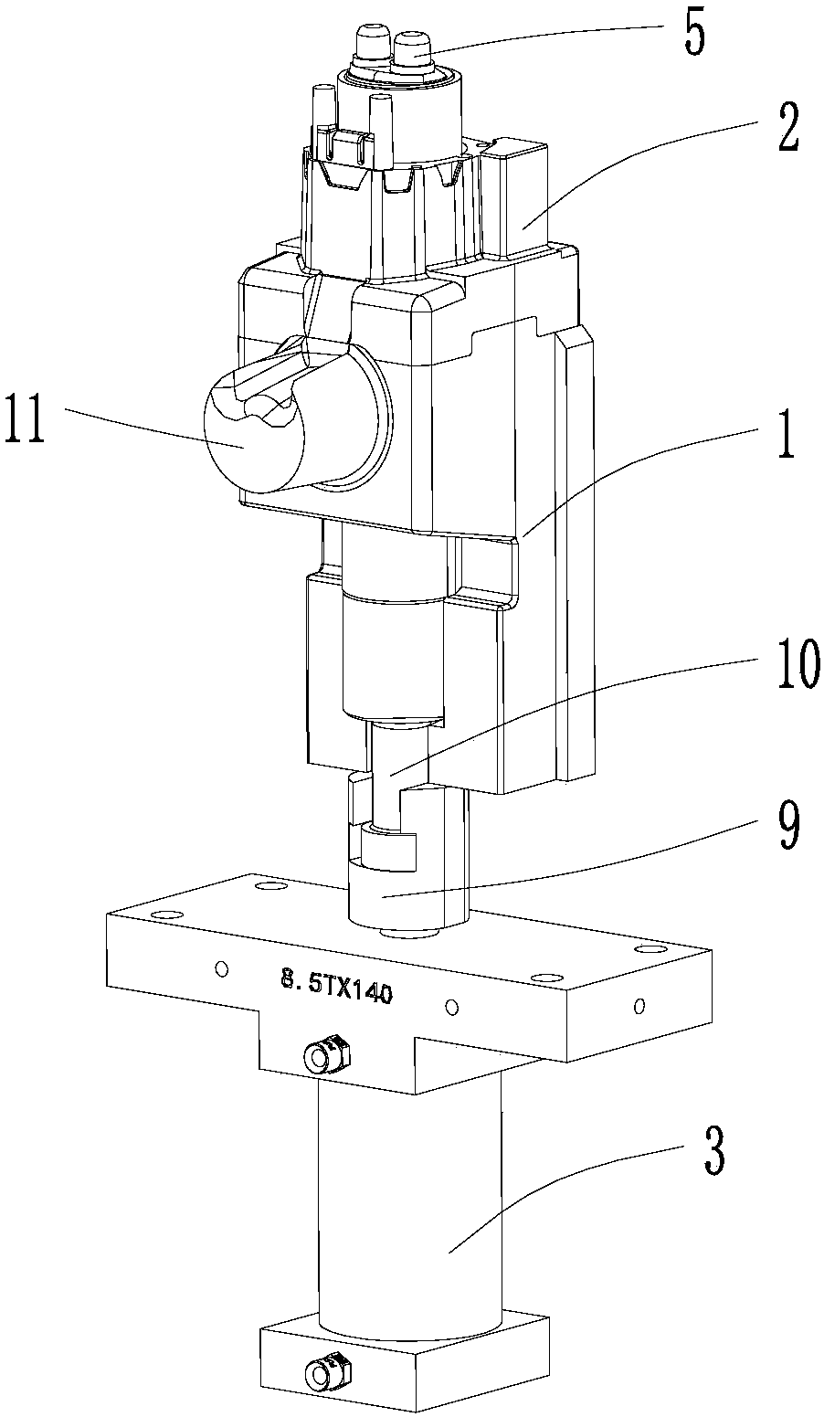
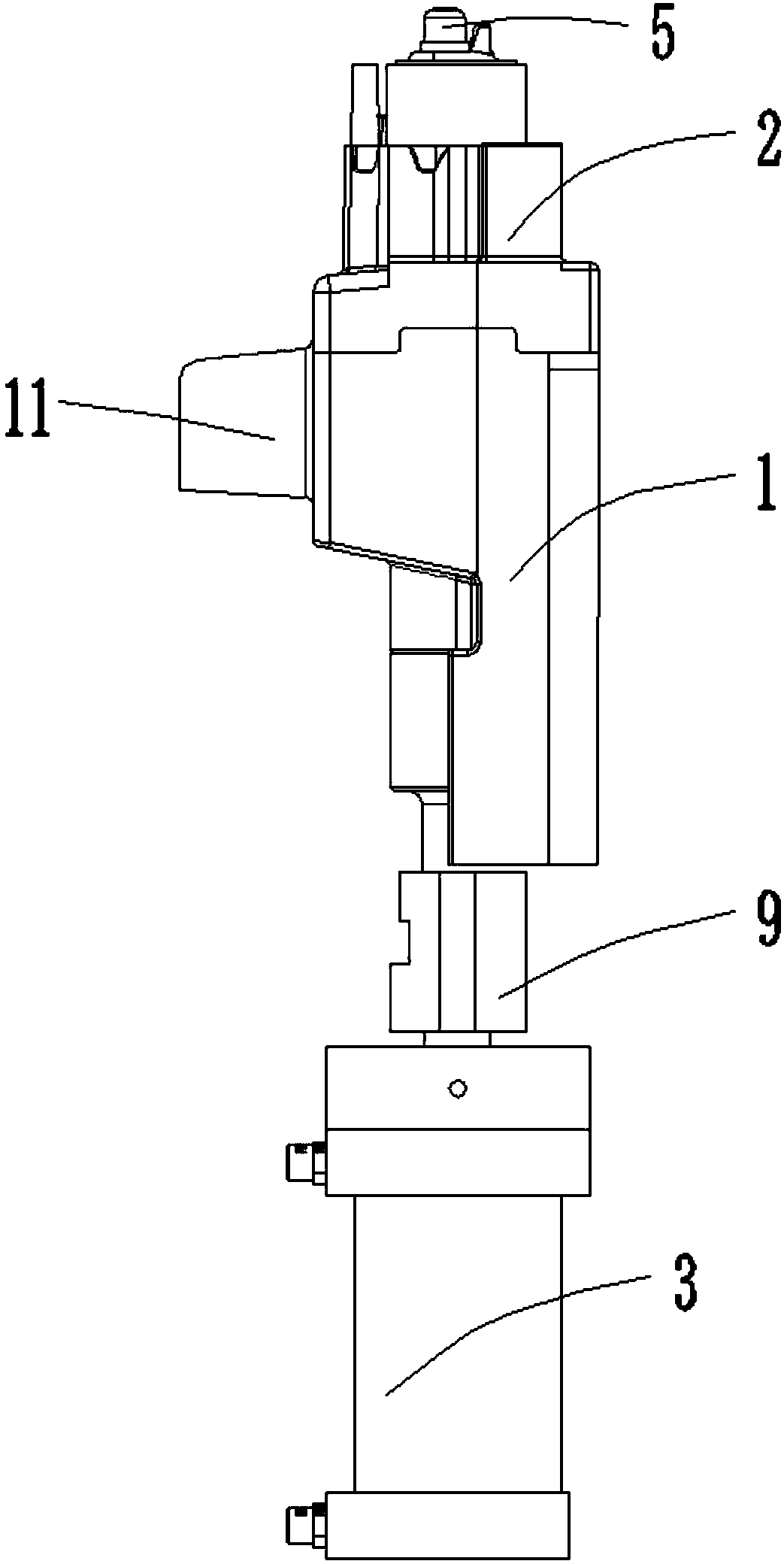
[0029] Such as Figure 1-7 As shown, a quick clamping device for a cylinder head and cylinder liner includes a slider 1, a slider 2, and an oil cylinder 3. The upper end of the slider 1 is fixedly connected to the lower end of the slider 2, and a Pull rod 4, the lower end of the pull rod 4 is connected with the piston rod of the oil cylinder 3, the top of the pull rod 4 stretches into the cylinder liner 5 provided in the slider 2, and the upper end of the pull rod 4 is provided with Guide chute 6, which is provided with a wedging block 7 in the guide chute 6, and a fixed block 8 is connected to the wedged block 7, and the outer end of the fixed block 8 can extend out of the cylinder liner column 5 for It is in contact with the inner wall of the cylinder liner to realize the expansion and fixation of...


PUM


Abstract

The invention discloses a fast clamping device for a cylinder head and a cylinder sleeve. The fast clamping device comprises a sliding seat, a sliding block and an oil cylinder, wherein the upper endof the sliding seat is fixedly connected with the lower end of the sliding block, and a pull rod penetrates through the sliding seat; the lower end of the pull rod is connected with a piston rod of the oil cylinder, and the upper portion of the pull rod extends into a cylinder sleeve column arranged inside the sliding block; guide sliding grooves are formed in the upper end of the pull rod, wedgeblocks are arranged in the guide sliding grooves, and fixing blocks are connected to the wedge blocks; and the outer ends of the fixing blocks can extend out of the cylinder sleeve column, and are used for being in contact with the inner wall of the cylinder sleeve so as to realize expansion and fixation of the cylinder sleeve. The fast clamping device for the cylinder head and the cylinder sleevehas the remarkable effects that the cylinder sleeve is well clamped and positioned in die-cast molding of the cylinder head, so that the shaking and displacement of the cylinder sleeve are avoided, positioning is accurate, coaxiality of machined products is good, and the product quality is high.

Description

technical field [0001] The invention relates to the technical field of engine component production, in particular to a quick clamping device for a cylinder head and liner. Background technique [0002] The cylinder head, commonly known as the cylinder head, is installed on the top of the cylinder block, seals the cylinder from the top and forms the combustion chamber, and is an important part of the engine together with the cylinder liner. In the high-temperature working environment, the cylinder liner bears the reciprocating frictional motion of the piston ring, so it is required to have good anti-wear and anti-high temperature fatigue performance. In order to ensure that the cylinder liner has good wear resistance and high temperature fatigue resistance, a good fit between the cylinder liner and the cylinder head is required. [0003] With the current development trend of the engine, the explosion pressure of the engine is getting higher and higher (the maximum explosion ...

Claims


Application Information

Patent Timeline
Patent Type & Authority Applications(China)
IPC IPC(8): B22D17/20
CPCB22D17/20
Inventor 高仲华邹世贵高星
Owner CHONGQING BORUN MOLD CO LTD
Why Eureka
Try Eureka