
Evaporating pot with efficient juice catching function

An evaporative tank and high-efficiency technology, applied in evaporation, evaporator accessories, chemical instruments and methods, etc., can solve the problems of energy waste, water waste, heat energy cannot be recycled and reused, etc., to reduce energy waste, reduce cooling water consumption, The effect of enhancing environmental performance

Inactive Publication Date: 2018-07-27
南安初盼商贸有限公司
View PDF0 Cites 3 Cited by
  • Summary
  • Abstract
  • Description
  • Claims
  • Application Information

AI Technical Summary

Problems solved by technology

[0004] Aiming at the deficiencies in the prior art, the object of the present invention is to provide an evaporation tank capable of efficiently capturing juice, so as to solve the problem that the evaporation tank in the prior art cannot convert the heat energy generated during the cooling process of the juice capture into electrical energy to provide electrical energy for evaporation, cooling The final hot water is directly discharged. On the one hand, the heat energy cannot be recycled and reused, resulting in energy waste, and on the other hand, it causes the defect of water waste.

Method used


Image

  • Evaporating pot with efficient juice catching function
  • Evaporating pot with efficient juice catching function
  • Evaporating pot with efficient juice catching function

Examples


Embodiment Construction

[0023] In order to make the technical means, creative features, goals and effects achieved by the present invention easy to understand, the present invention will be further described below in conjunction with specific embodiments.

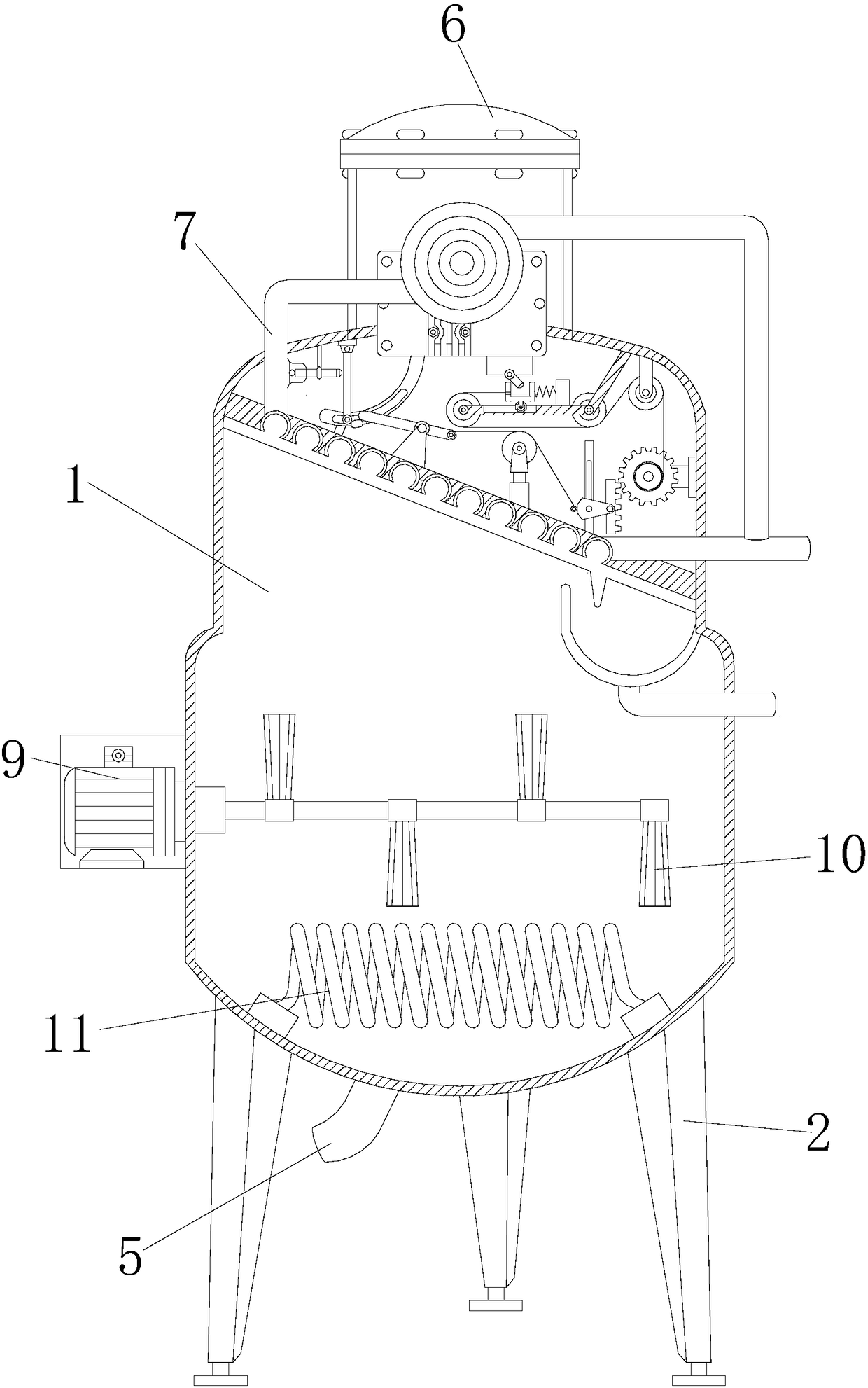
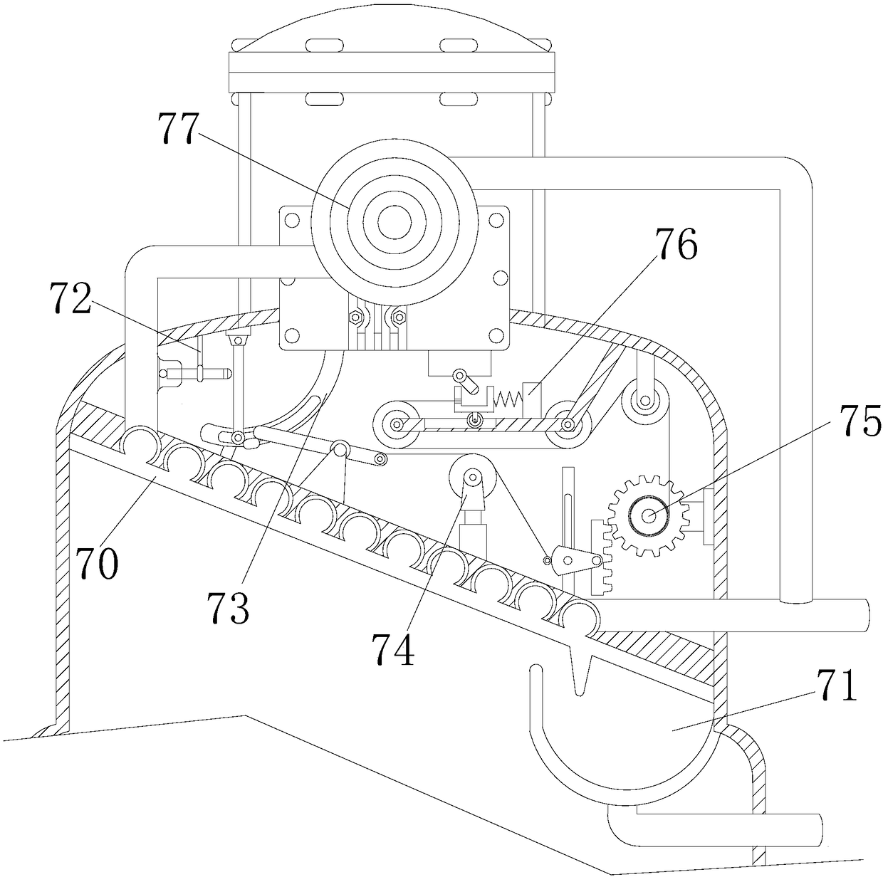
[0024] see Figure 1-Figure 5 , the present invention provides a technical scheme of an evaporation tank that can efficiently capture juice: its structure includes a tank body 1, a support stand 2, a feed port 3, a sealing cover 4, a waste liquid discharge pipe 5, a maintenance port 6, a recyclable Heat energy juice trapping device 7, distillate outlet pipe 8, motor box 9, stirring device 10, resistance heater 11, the tank body 1 is in a cylindrical structure, and the support tripod 2 is arranged under the tank body 1 and connected by electric welding. connected, the feed inlet 3 is arranged on the upper part of the front surface of the tank body 1, and it has an integrated structure with it, the sealing cover 4 is arranged in front of the feed in...


PUM


Abstract

The invention discloses an evaporating pot with an efficient juice catching function. The evaporating pot structurally comprises a pot, support leg frames, a feed inlet, a sealing cover, a waste liquid drain pipe, a maintenance opening, a juice catching device with a heat energy recycling function, a distillate outlet pipe, a motor tank, stirring devices and a resistance heater. The pot is of a cylinder structure, the support leg frames are arranged on the lower side of the pot and are connected with the pot by means of electric welding, the feed inlet is formed in the upper portion of the front surface of the pot, the feed inlet and the upper portion of the front surface of the pot are of integrally formed structures, the sealing cover is arranged at the front of the feed inlet and is movably connected with the pot by hinges, and the waste liquid drain pipe is arranged on the lower side of the pot and is communicated and connected with the pot by means of electric welding. The evaporating pot has the advantages that heat energy generated in juice catching cooling can be converted into electric energy by the juice catching device with the heat energy recycling function, the electric energy can be supplied for equipment such as the stirring devices and heating devices with electric power utilization requirements, accordingly, energy can be recycled, and energy waste can be reduced; cooling water can be repeatedly recycled, accordingly, cooling water consumption can be reduced, and the environmental protection performance of the evaporating pot with the efficient juice catching function can be effectively enhanced.

Description

technical field [0001] The invention is an evaporation tank capable of efficiently capturing juice, belonging to the field of evaporation tanks. Background technique [0002] Evaporation tanks are widely used in liquid concentration processes, especially the evaporation of concentrated seawater to produce salt, the evaporation of underground saturated brine to produce salt, and the production of potassium chloride by evaporation of bittern are all completed by evaporation tanks. It has the dual advantages of glass stability and metal strength, and is an excellent corrosion-resistant equipment, widely used in chemical, petroleum, pharmaceutical, pesticide, food and other industries. [0003] However, the evaporating tanks in the prior art cannot convert the heat energy generated during the juice catching and cooling process into electric energy to provide electric energy for the evaporation work, and the cooled hot water is discharged directly. waste. Contents of the inven...

Claims


Application Information

Patent Timeline
IPC IPC(8): B01D1/00B01D1/30
CPCB01D1/00B01D1/0017B01D1/30
Inventor 王斌汪宗成邵金元
Owner 南安初盼商贸有限公司
Learn More