Automatic electronic product assembling device and assembling manipulator thereof

A technology for automation group and electronic products, applied in the direction of electrical components, electrical components, etc., can solve the problems of cumbersome operation, long assembly line, difficult positioning and alignment, etc.

Pending Publication Date: 2018-07-24
SHENZHEN XING GRAIN AUTOMATION CO LTD
View PDF6 Cites 7 Cited by
  • Summary
  • Abstract
  • Description
  • Claims
  • Application Information

AI Technical Summary

Problems solved by technology

Based on this, in the production and assembly process of electronic products, it is necessary to fix the product and then assemble various electronic components into the product; at present, most production companies use assembly lines to complete the assembly manually. Due to the large number of spare parts for a single product, Moreover, the shapes and sizes of spare parts are different, and multiple stations need to be arranged to complete the assembly. The assembly line is long, the assembly efficiency is low, and it is difficult to ensure the stability and consistency of the assembly quality.
Automatic assembly of electronic product spare parts is the future development trend. However, due to the small size and various shapes of electronic components, there are technical difficulties in the process of automatic design: 1. The positioning and alignment in the assembly process is difficult. 2. The assembly accuracy is difficult to meet the requirements; 3. The assembly manipulator has poor versatility, and a single manipulator cannot complete the assembly of various electronic components, resulting in frequent replacement of manipulators in the actual assembly process, cumbersome operation, and high cost

Method used


Image

  • Automatic electronic product assembling device and assembling manipulator thereof
  • Automatic electronic product assembling device and assembling manipulator thereof
  • Automatic electronic product assembling device and assembling manipulator thereof

Examples


Embodiment 1

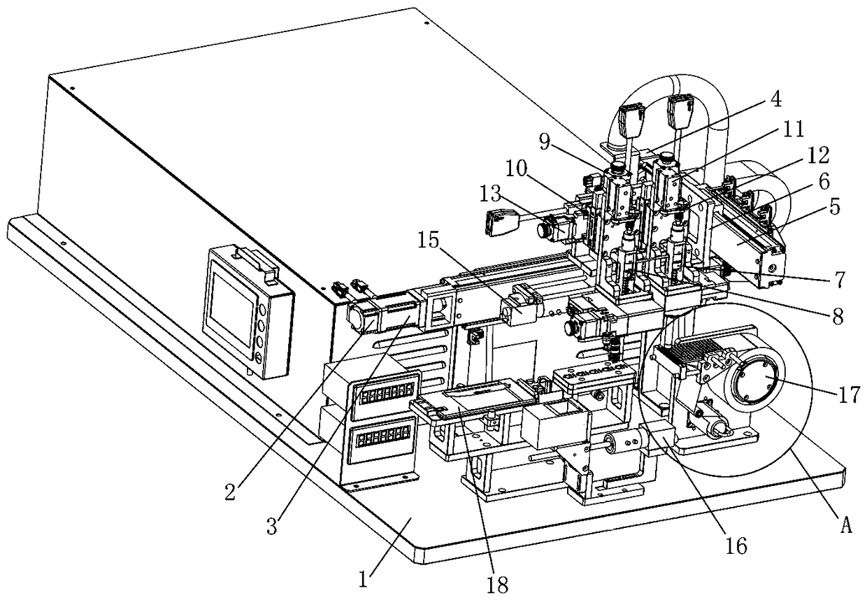
[0043] Embodiment 1: as Figure 1 to Figure 8 As shown, the technical solution adopted in Embodiment 1 of the present invention is as follows: an automatic assembly machine for electronic products, including a drive mechanism, a slide seat 6, a fine-tuning mechanism, a CCD mechanism, a feeding mechanism 17, a first assembly manipulator 7 and a second assembly Manipulator 8, wherein, the above-mentioned drive mechanism is arranged on the machine platform 1, and the drive mechanism includes a horizontal assembly, a vertical assembly connected to the horizontal assembly and a lifting assembly; the above-mentioned slide seat 6 is connected with the output end of the vertical assembly, and is passed through the horizontal assembly and the vertical assembly. The longitudinal assembly is driven to move linearly in the horizontal plane; the slide seat 6 is provided with two installation stations; The output ends are respectively arranged along the longitudinal direction and the transv...

Embodiment 2

[0064] Embodiment 2: as Figure 9 with Figure 10 As shown, it is a schematic diagram of the three-dimensional structure of the assembly manipulator in Embodiment 2 of the present invention. This embodiment can realize the pick-and-place and assembly of hard sheet materials such as cover plate c; the shaft arm, transmission assembly, and pressure sensor of this embodiment And the material suction assembly is the same as in embodiment 1; the vacuum adsorption material can be realized by the vacuum adsorption head 018 arranged at the lower end of the slide bar, and the real-time sensing of pressure when taking materials or assembling is realized by using a pressure sensor; the difference from embodiment 1 is In this embodiment, the clamping assembly is directly arranged on the slide bar, specifically: the transmission sleeve 016 of this embodiment is directly set on the lower part of the slide bar 08, and the support rod 014 in Example 1 is omitted. The structural design is sim...

Embodiment 3

[0065] Embodiment 3: as Figure 11 to Figure 13As shown, it is a schematic diagram of the three-dimensional structure of the assembly manipulator in Embodiment 3 of the present invention. The assembly manipulator of this embodiment is mainly used for picking and placing or assembling dual cameras, and the dual cameras include a first camera d and a second camera e; The shaft arm, transmission assembly, pressure sensor, and material suction assembly are the same as in Embodiment 1, and the first camera d is absorbed by the vacuum suction head at the lower end of the slide bar 08; the difference from Embodiment 1 is that the sleeve of the material clamping assembly in this embodiment 010 is not connected and fixed on the slide bar 08, but is fixedly connected to the lifting slide seat 10 of the lifting assembly, and extends to the side of the slide bar 08, and synchronizes the movement of the slide bar 08; the material clamping assembly of the present embodiment Cylinder 011, pr...


PUM


Abstract

The invention discloses an automatic electronic product assembling device and an assembling manipulator thereof. The assembling device comprises a driving mechanism, a slide seat, two fine tuning mechanisms, a CCD mechanism, a feeding mechanism and first and second assembling manipulators; the driving mechanism is arranged on a workbench, and comprises a horizontal assembly, and a vertical assembly and two elevating assemblies connected to the horizontal assembly; the slide seat is connected with the output end of the vertical assembly; the slide seat is provided with two installation stations; the two fine tuning mechanisms are arranged in the two installation stations of the slide seat respectively; the two elevating assemblies are arranged in the two installation stations of the slide seat respectively; the first and second assembling manipulators are arranged in the external sides of the elevating assemblies respectively, and connected to the output ends of the elevating assembliesrespectively; and each CCD mechanism comprises an upper CCD assembly and a lower CCD assembly. According to the invention, materials are aligned with product assembly portions accurately, the assembling precision is high, and different electronic components are assembled.

Description

technical field [0001] The invention relates to the field of mechanical automation, in particular to an electronic product automatic assembly machine and its assembly manipulator. Background technique [0002] In recent years, smart electronic products have developed rapidly, such as smart phones, notebook computers, IPADs and other products; the wide use of electronic products has become an indispensable tool in people's daily production and life; electronic products generally use PCB boards as functional integration carriers, Connect various electronic components (such as camera, tamper-proof sticker, gland, cable, connector, etc.) marking, electrical connection, etc. Based on this, during the production and assembly process of electronic products, it is necessary to fix the product and then assemble various electronic components into the product; at present, most production companies use assembly lines to complete the assembly manually. Due to the large number of spare p...

Claims


Application Information

Patent Timeline
Patent Type & Authority Applications(China)
IPC IPC(8): H05K13/08H05K13/04
CPCH05K13/0408H05K13/0417H05K13/08
Inventor 章胜华宋亚龙
Owner SHENZHEN XING GRAIN AUTOMATION CO LTD
Why Eureka
Try Eureka