
Group pile displacement determination method and apparatus

A displacement and pile group technology, which is applied in special data processing applications, instruments, electrical and digital data processing, etc., can solve the problems of low calculation accuracy of pile group displacement, and achieve the effect of solving the low calculation accuracy and improving the calculation accuracy.

Inactive Publication Date: 2018-07-24
CHNA ENERGY INVESTMENT CORP LTD +1
View PDF2 Cites 2 Cited by
  • Summary
  • Abstract
  • Description
  • Claims
  • Application Information

AI Technical Summary

Problems solved by technology

[0009] The embodiment of the present invention provides a method and device for determining the displacement of a pile group, at least to solve the technical problem that the calculation accuracy of the displacement of the pile group is low due to the lack of consideration of the mutual influence between the foundation piles in the pile group

Method used


Image

  • Group pile displacement determination method and apparatus
  • Group pile displacement determination method and apparatus
  • Group pile displacement determination method and apparatus

Examples


Embodiment 1

[0036] According to an embodiment of the present invention, an embodiment of a method for determining the displacement of a pile group is provided. It should be noted that the steps shown in the flow chart of the accompanying drawings can be executed in a computer system such as a set of computer-executable instructions, and , although a logical order is shown in the flowcharts, in some cases the steps shown or described may be performed in an order different from that shown or described herein.

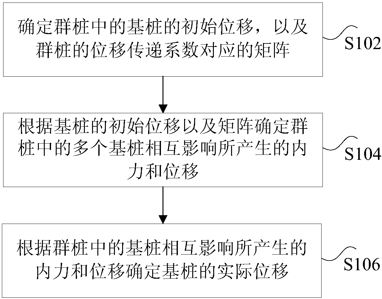
[0037] figure 1 is a flow chart of a method for determining displacement of pile groups according to an embodiment of the present invention, such as figure 1 As shown, the method includes the following steps:

[0038] Step S102, determining the initial displacement of the foundation piles in the pile group and a matrix corresponding to the displacement transfer coefficient of the pile group, wherein the pile group includes a plurality of foundation piles.

[0039] It should be note...

Embodiment 2

[0191] According to an embodiment of the present invention, an embodiment of a device for determining displacement of pile groups is also provided, wherein, Figure 12 is a structural schematic diagram of a device for determining displacement of pile groups according to an embodiment of the present invention, such as Figure 12 As shown, the device includes: a determination module 1201 , a first determination module 1203 and a second determination module 1205 .

[0192] Wherein, the determination module 1201 is used to determine the initial displacement of the foundation pile in the pile group and the matrix corresponding to the displacement transfer coefficient of the pile group, wherein the pile group includes a plurality of foundation piles; the first determination module 1203 is used to The initial displacement of the pile and the matrix determine the internal force and displacement generated by the interaction of multiple foundation piles in the pile group; the second det...

Embodiment 3

[0214] According to another aspect of the embodiments of the present invention, a storage medium is also provided, the storage medium includes a stored program, wherein the program executes the method for determining pile group displacement in Embodiment 1.


PUM


Abstract

The invention discloses a group pile displacement determination method and apparatus. The method comprises the steps of determining initial displacements of foundation piles in group piles and a displacement transfer coefficient matrix of the group piles; according to the initial displacements of the foundation piles and a displacement transfer coefficient, determining internal forces and displacements generated by mutual influence of the foundation piles in the group files; and according to mutual influence parameters, determining the internal forces and the displacements of the foundation piles in the group files. The technical problem of relatively low calculation precision of group pile displacement due to no consideration of mutual influence between the foundation piles in the group piles and the foundation piles is solved.

Description

technical field [0001] The invention relates to the field of civil engineering, in particular to a method and a device for determining displacement of pile groups. Background technique [0002] Cap pile group foundation is a relatively common form of foundation, widely used in high-rise buildings, railway bridges, energy and other industries. How to accurately calculate the displacement and internal force of pile groups under vertical and horizontal loads is the focus of pile group analysis, which is of great significance to the design and construction of pile group foundations. [0003] Pile group loading is divided into vertical loading and horizontal loading. At present, there are two main methods for calculating the internal force of vertical displacement of pile group: [0004] 1) Numerical calculation method [0005] Numerical calculation methods include boundary element method, finite element method or difference method. The numerical calculation method takes into ...

Claims


Application Information

Patent Timeline
Patent Type & Authority Applications(China)
IPC IPC(8): G06F17/50
CPCG06F30/13G06F30/23
Inventor 李早
Owner CHNA ENERGY INVESTMENT CORP LTD
Learn More