Iron anchor structure for detecting tsunamis

A technology of tsunami and iron anchors, applied in seismology, measuring devices, geophysical surveys, etc. for areas covered by water, can solve problems such as increased space occupancy, damage, and failure to satisfy customers, and achieve occupancy savings , easy to use, avoid the effect of precision

Inactive Publication Date: 2018-07-24
NANAN ZHINENGLAN IND DESIGN
View PDF0 Cites 0 Cited by
  • Summary
  • Abstract
  • Description
  • Claims
  • Application Information

AI Technical Summary

Problems solved by technology

[0002] A tsunami is a catastrophic wave. After a shock, the shock wave spreads to a long distance in an expanding circle on the sea surface. It is so powerful that it will cause devastating damage. Therefore, the occurrence of a tsunami often causes Huge economic losses and some irreparable lives. Therefore, the detection and early warning of tsunami is very important, so that people around can have a certain buffer time to reduce the damage caused by tsunami, because tsunamis are usually erupted by submarine volcanoes Or it is caused by an earthquake, so the tsunami is generally detected and predicted by detecting the vibration on the seabed. The iron anchor structure used to detect the tsunami cannot be fixed on the seabed when the anchor is lowered to the seabed, causing the anchor Severe shaking on the seabed affects the detection effect of the tsunami monitoring device and affects the accuracy of the detection data. At the same time, when the iron anchor is retracted, the iron anchor cannot be retracted into the inside of the machine, which greatly increases the space occupancy rate. At the same time, the iron anchor It is placed outside the machine. When the machine is moving, the iron anchor will scrape foreign objects in the water and get stuck. It requires the staff to manually handle the operation of the contact fault, which is inconvenient for the staff to use and cannot meet the needs of customers.

Method used


Image

  • Iron anchor structure for detecting tsunamis
  • Iron anchor structure for detecting tsunamis
  • Iron anchor structure for detecting tsunamis

Examples


Embodiment Construction

[0018] The following will clearly and completely describe the technical solutions in the embodiments of the present invention with reference to the accompanying drawings in the embodiments of the present invention. Obviously, the described embodiments are only some, not all, embodiments of the present invention. Based on the embodiments of the present invention, all other embodiments obtained by persons of ordinary skill in the art without making creative efforts belong to the protection scope of the present invention.

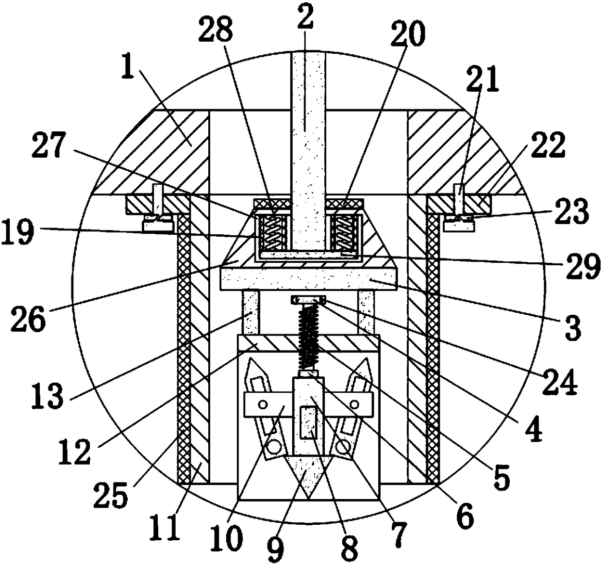
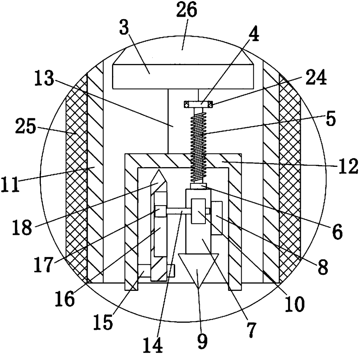
[0019] see Figure 1-3 , the present invention provides a technical solution: an iron anchor structure for detecting tsunami, including a platform 1 and a sleeve 11, the platform 1 can float in sea water, the middle of the bottom end of the platform 1 is welded with a sleeve 11, the sleeve The outer wall of 11 is sleeved with rubber ring 25, and rubber ring 25 can play the effect of protecting rubber ring 25, prevents sleeve 11 from being damaged by foreign ma...


PUM


Abstract

The invention discloses an iron anchor structure for detecting tsunamis. The iron anchor structure comprises a platform and a sleeve, wherein the sleeve is welded in the middle of the bottom end of the platform; a top plate is arranged at the top end inside the sleeve; a steel rope is mounted at the top end of the top plate; the steel rope penetrates through the platform; a bracket is arranged atthe bottom end of the top plate; the left side and the right side of the top end of the bracket are both connected with the top plate through support columns in a welded manner. By adopting the iron anchor structure for detecting tsunamis, with the combination of an anchor rod and a top tip, the top tip can be inserted into a seabed and fixed, the anchor rod can be prevented from acute shaking which can affect detection results of a tsunami monitoring device at the seabed, the precision degree of detection data is not affected, with the combination of a sliding block and a first hinge pin, a rotating rod can be rotationally expanded to leave off the interior of the bracket or can be folded up and stored, and meanwhile the consequence that the connecting rod scraps a foreign matter and is clamped and cannot be moved when being expanded, retained in seawater and is moved along with the platform, can be avoided.

Description

technical field [0001] The invention relates to the technical field of iron anchor structures, in particular to an iron anchor structure for detecting tsunamis. Background technique [0002] A tsunami is a catastrophic wave. After a shock, the shock wave spreads to a long distance in an expanding circle on the sea surface. It is so powerful that it will cause devastating damage. Therefore, the occurrence of a tsunami often causes Huge economic losses and some irreparable lives. Therefore, the detection and early warning of tsunami is very important, so that people around can have a certain buffer time to reduce the damage caused by tsunami, because tsunamis are usually erupted by submarine volcanoes Or it is caused by an earthquake, so the tsunami is generally detected and predicted by detecting the vibration on the seabed. The iron anchor structure used to detect the tsunami cannot be fixed on the seabed when the anchor is lowered to the seabed, causing the anchor Severe s...

Claims


Application Information

Patent Timeline
IPC IPC(8): G01V1/18G01V1/38G08B21/10
CPCG01V1/181G01V1/186G01V1/3808G08B21/10Y02A50/00
Inventor 林建铃
Owner NANAN ZHINENGLAN IND DESIGN
Why Eureka
Try Eureka