
Road surface washing device

A technology for road surface cleaning and flushing holes, which is applied in road surface cleaning, cleaning methods, construction, etc., can solve the problems of flying dust, high maintenance cost, and large watering investment, so as to save manpower and material resources, simple and convenient maintenance, and good flushing effect Effect

Inactive Publication Date: 2018-07-24
河南省隆邦勘测规划设计工程有限公司
View PDF0 Cites 0 Cited by
  • Summary
  • Abstract
  • Description
  • Claims
  • Application Information

AI Technical Summary

Problems solved by technology

[0002] In the process of urbanization, the evolution of roads is becoming more and more modern. At present, the main materials of roads in cities are asphalt roads and cement roads. Due to the increase in traffic volume and the decline in air quality, there are more and more dirt on the road surface. , the speed of deposition is getting faster and faster, and due to the driving of vehicles, the dust is flying, which seriously affects the air quality and affects people's health. Therefore, in order to improve the beauty of the urban environment and the improvement of air quality, the municipal departments need to frequently water the roads Treatment and sprinkling require maintenance personnel to use sprinklers to carry out sprinkling operations. Sprinkling with sprinklers requires more investment, higher maintenance costs, and more personnel input. Therefore, the current municipal government needs a convenient technical solution for road cleaning

Method used


Image

  • Road surface washing device

Examples


Embodiment Construction

[0013] The present invention will be further described below in conjunction with the accompanying drawings and embodiments.

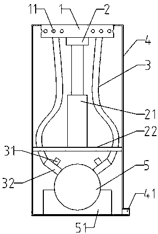
[0014] Such as figure 1 As shown, a road surface cleaning device includes a flushing plate 1, a support rod 2, a jacking cylinder 21, a cylinder support plate 22, a water supply main pipe 5, a water supply branch pipe and a casing 4. The flushing hole 11 provided on the flushing plate 1 is located in the flushing area. Both sides of the disk 1 are symmetrical to each other, and the lower end of the casing 4 is provided with a drainage hole 41. The flushing disk 1, the support rod 2, the jacking cylinder 21, the cylinder support plate 22, the main water supply pipe 5 and the water supply branch pipe are all arranged in the casing 4, wherein the casing 4 The upper end is provided with a protruding hole, the flushing tray 1 is located in the protruding hole, the lower end of the flushing tray 1 is fixed on the support rod 2, the lower end of the support ro...


PUM


Abstract

The invention discloses a road surface washing device which comprises a washing disc, a supporting rod, a jacking air cylinder, an air cylinder supporting board, a water feeding main pipe, water feeding branch pipes and a shell. An extend-out hole is formed in the upper end of the shell. The washing disc is located in the extend-out hole. The lower end of the washing disc is fixed to the supporting rod. The lower end of the supporting rod is connected to the jacking air cylinder. The jacking air cylinder is vertically arranged, and the lower end of the jacking air cylinder is fixed to the aircylinder supporting board. The air cylinder supporting board is horizontally arranged in the shell. The water feeding main pipe is arranged below the air cylinder supporting board. A fixing block is arranged on the lower portion of the water feeding main pipe and arranged at the bottom of the shell. Each water feeding branch pipe comprises a fixed branch pipe and a movable branch pipe. The fixed branch pipes are arranged on one side of the water feeding main pipe. One end of each movable branch pipe is connected to the corresponding fixed branch pipe, and the other end of each movable branch pipe penetrates through the air cylinder supporting board to be connected with the washing disc. Electromagnetic valves are arranged on the fixed branch pipes. Multiple washing holes are formed in thewashing disc. The road surface washing device is easy and convenient to maintain, easy to control, capable of saving plenty of manpower and material resources and good in washing effect.

Description

technical field [0001] The invention relates to the field of road surface cleaning devices, in particular to a road surface cleaning device. Background technique [0002] In the process of urbanization, the evolution of roads is becoming more and more modern. At present, the main materials of roads in cities are asphalt roads and cement roads. Due to the increase in traffic volume and the decline in air quality, there are more and more dirt on the road surface. , the speed of deposition is getting faster and faster, and due to the driving of vehicles, dust is flying, which seriously affects the air quality and affects people's health. Therefore, in order to improve the beauty of the urban environment and the improvement of air quality, the municipal departments need to frequently sprinkle water on the roads Treatment and sprinkling requires maintenance personnel to use sprinklers to carry out watering operations. Using sprinklers requires more investment in watering, higher ...

Claims


Application Information

Patent Timeline
Patent Type & Authority Applications(China)
IPC IPC(8): E01H1/10
CPCE01H1/101
Inventor 司会贞
Owner 河南省隆邦勘测规划设计工程有限公司
Learn More