Cathodic-disbonding knife device

A cathode stripping and stripping knife technology, which is applied in the electrolysis process, electrolysis components, etc., can solve the problems of occupying a relatively large processing space, unfavorable streamlining procedures, and residual metal plates, so as to achieve high stripping efficiency and improve the success rate of pre-stripping , easy-to-control effects

Pending Publication Date: 2018-07-24
SANMEN SANYOU TECH CO LTD
View PDF5 Cites 1 Cited by
  • Summary
  • Abstract
  • Description
  • Claims
  • Application Information

AI Technical Summary

Problems solved by technology

[0002] The stripping procedures that are commonly used in the market at present are usually completed by a number of separate components that operate sequentially. This process requires multiple mechanical components. Multiple components lead to a process that requires a relatively large processing site. Moreover, the connection between multiple parts requires additional operation steps, which is not conducive to streamlining procedures in the production process, and the cost is relatively high; in addition, due to the strong adhesion of the plate-like attachments on the metal plate to the metal plate during the peeling process, it is not easy to It is beneficial to the stripping process, but it will cause unfavorable results such as incomplete stripping or residue on the metal plate

Method used


Image

  • Cathodic-disbonding knife device
  • Cathodic-disbonding knife device
  • Cathodic-disbonding knife device

Examples


Embodiment

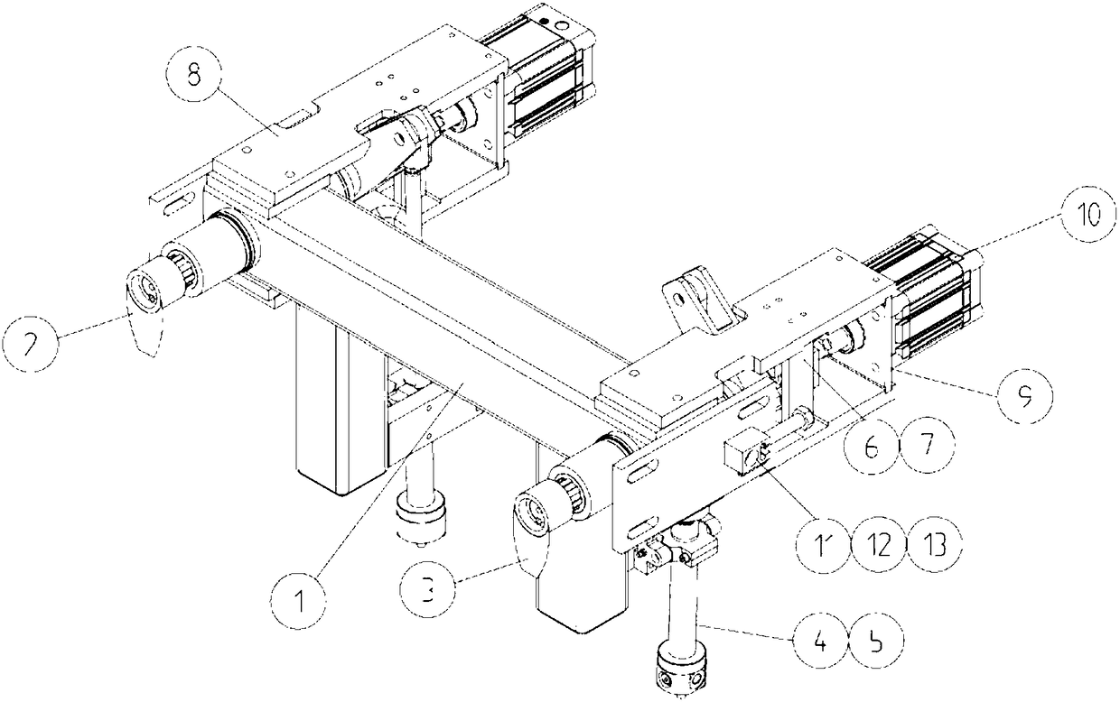
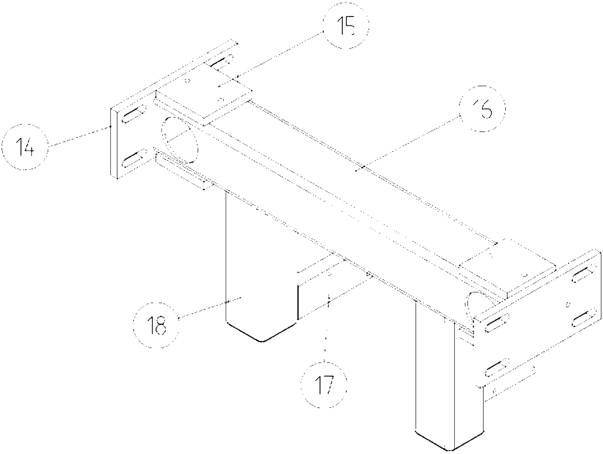
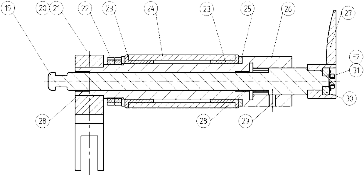
[0015] Embodiment: As shown in the drawings, this cathode stripping knife device mainly includes a stripping knife holder 1, a left stripping knife assembly 2, a right stripping knife assembly 3, a stripping knife rotary cylinder 5, a connecting plate 6, and a cylinder connecting block 7 , cylinder cover plate 8, cylinder mounting seat 9, stripping knife drive cylinder 10, left stripping knife assembly 2 and right stripping knife assembly 3 are installed symmetrically at both ends of stripping knife rest 1, and oil cylinder mounting seat 17 of stripping knife rest 1 is connected to the trunnion support Seat 4 and stripping knife rotary oil cylinder 5, left stripping knife assembly 2 and right stripping knife assembly 3 are connected with connecting plate one 6, cylinder connecting block 7, cylinder cover plate 8, and cylinder cover plate 8 tail end is connected cylinder mounting seat 9, cylinder The stripping knife driving cylinder 10 is installed on the mount 9, and the left s...


PUM


Abstract

The invention discloses a cathodic-disbonding knife device. The cathodic-stripping knife device mainly comprises a disbonding knife rest, disbonding knife components, a disbonding knife rotary oil cylinder and a disbonding knife driving air cylinder, wherein the left stripping knife component and the right stripping knife component are symmetrically arranged at the two ends of the stripping kniferest; an oil cylinder installing seat of the stripping knife rest is connected with a trunnion support and the disbonding knife rotary oil cylinder; the left disbonding knife component and the right disbonding knife component are connected with connecting plates I, air cylinder connecting blocks and air cylinder cover plates; the tail end of each air cylinder cover plate is connected with an air cylinder installing seat; the disbonding knife driving air cylinder is arranged on the air cylinder installing seat; the outer sides of the left disbonding knife component and the right disbonding knife component are also provided with adjusting blocks, adjusting bolts and adjusting-block supporting pipes. The cathodic-disbonding knife device disclosed by the invention has the beneficial effects that the benefit for realizing an automatic process of a copper stripping unit is achieved, the structure is simple and reliable, the stripping efficiency is high, the surface of a cathode plate is protected from being damaged, and the noise at a production site can be reduced; by environment-friendly and reasonable knife design, the surface damage of stainless steel can be reduced, and the pre-disbonding success ratio can be increased; the cathodic-disbonding knife device is simple in structure, good in practicability and easy to control.

Description

technical field [0001] The invention relates to the field of hydrometallurgy tools, in particular to a cathode stripping knife device. Background technique [0002] The stripping procedures that are commonly used in the market at present are usually completed by a number of separate components that operate sequentially. This process requires multiple mechanical components. Multiple components lead to a process that requires a relatively large processing site. Moreover, the connection between multiple parts requires additional operation steps, which is not conducive to streamlining procedures in the production process, and the cost is relatively high; in addition, due to the strong adhesion of the plate-like attachment on the metal plate during the peeling process, it is not easy to It is beneficial to the stripping process, but it will cause unfavorable results such as incomplete stripping or residue on the metal plate. Contents of the invention [0003] The purpose of th...

Claims


Application Information

Patent Timeline
Patent Type & Authority Applications(China)
IPC IPC(8): C25C7/08
CPCC25C7/08
Inventor 吴用吴俊义杨攀周成武李至青
Owner SANMEN SANYOU TECH CO LTD
Why Eureka
Try Eureka