


Quick Research
Generate reliable direction feasibility study reports for your R&D in just a few steps.

Technical Q&A
Discover and master advanced knowledge NOW. Basics, ideas, possibilities, all at once.

Find Solutions
As an expert in R&D theories, this can generate solutions to your technical problems instantly.

Evaluate Feasibility
Analyze your overall solution with one click, know your potential R&D risks in advance.

Monitor Landscape
Get weekly tech updates, stay abreast of the latest tech innovations and key insights.
Automatic real-time liquid discharging device
A liquid discharge device and automatic technology, applied in distribution devices, liquid flow control devices, special distribution devices, etc., can solve the problems of high operator dependence, failure to operate according to time nodes, and failure to discharge liquid, etc. Achieve the effects of wide application range, simple structure and improved work efficiency
- Summary
- Abstract
- Description
- Claims
- Application Information
AI Technical Summary
Problems solved by technology
Method used
Image


Examples
Embodiment 1
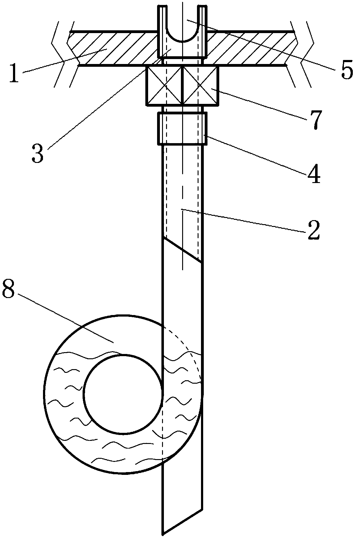
[0023] refer to figure 2 As shown, it is a specific embodiment of the present invention, which is also provided with a bent tube 8 arranged at the end of the hollow tube 2. Preferably, the bent tube 8 is the end first along the hollow tube 2. The transparent plastic tube that is bent in the direction of the top and then arranged circuitously along the direction of the bottom of the hollow tube 2 is used in the occasion where the box body needs to isolate the inner and outer spaces. In the actual use process, the transparent plastic tube is inserted into the Hollow tube 2, then wound around and tightened to form a water bend sealed structure, using the principle of water bend to realize the isolation of the inner and outer space of the box, and the liquid can also be drained to the designated place through the bend.
Embodiment 2
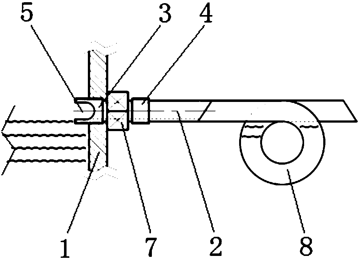
[0025] refer to image 3 As shown, it is another specific embodiment of the present invention, which is basically the same as Embodiment 1, except that the first connecting part 3 is connected with the side wall of the box body 1, so that the draining device is connected with the bottom surface of the box body 1 There is a certain height distance, which is set according to actual needs, and the structural position of the water bend seal can be changed by adjusting the height of the bent tube 8, so as to adjust the height of the liquid level in the tank, which is convenient for adjustment. This embodiment applies It is suitable for tanks with limited liquid level, and has a wide range of applications.
Embodiment 3
[0027] refer to Figure 4 As shown, it is another specific embodiment of the present invention, which is basically the same as Embodiment 1, the difference is that the liquid discharge device of this embodiment also includes a container for receiving liquid arranged under the hollow tube 2 bottle 9, a bottle cap 10 connected to the containing bottle 9 and sleeved on the second connecting part 4, and a compression nut 11 located below the bottle cap 10 and screwed on the second connecting part 4, wherein the containing bottle 9 surrounds the lower part of the hollow tube 2, the bent tube 8 and the compression nut 11, and the discharged liquid is collected in the holding bottle 9. Preferably, the outer wall of the top of the holding bottle 9 has external threads, and correspondingly, the inner wall of the bottle cap 10 It has an internal thread, and the bottle cap 10 is detachably screwed to the top of the holding bottle 9, which is convenient for disassembly. When the liquid is...
PUM
 Abstract
Description
Claims
Application Information
 - R&D Engineer
- R&D Manager
- IP Professional
- Industry Leading Data Capabilities
- Powerful AI technology
- Patent DNA Extraction
Browse by: Latest US Patents, China's latest patents, Technical Efficacy Thesaurus, Application Domain, Technology Topic, Popular Technical Reports.
© 2024 PatSnap. All rights reserved.Legal|Privacy policy|Modern Slavery Act Transparency Statement|Sitemap|About US| Contact US: help@patsnap.com