
Novel 3D printer nozzle structure

A technology of 3D printers and nozzles, applied in the field of printing, can solve the problems of wasting manpower and time, lack of multi-color application, and poor viewing of items, etc., and achieve good circulation or interception, and facilitate thermal treatment.

Pending Publication Date: 2018-07-24
TIANJIN ZHIJIE TECH CO LTD
View PDF9 Cites 3 Cited by
  • Summary
  • Abstract
  • Description
  • Claims
  • Application Information

AI Technical Summary

Problems solved by technology

[0003] The purpose of the present invention is to provide a new type of 3D printer nozzle structure to solve the problem that the traditional 3D printing nozzle proposed in the above background technology is a single feeding mechanism, which does not have a good function of using multiple colors, and will be wasted when changing colors. A lot of manpower and time, and when the color is scarce, the printed items do not have good viewing

Method used


Image

  • Novel 3D printer nozzle structure
  • Novel 3D printer nozzle structure
  • Novel 3D printer nozzle structure

Examples


Embodiment 1

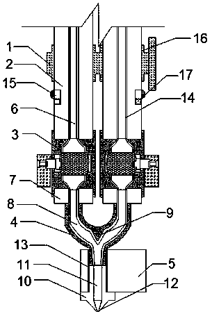
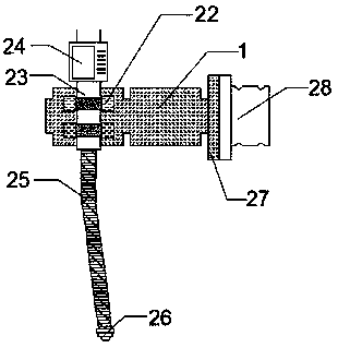
[0022] like Figure 1-3 As shown, a new 3D printer nozzle structure includes a sleeve frame 1, a delivery pipe 2, a miniature ball valve 3, a confluence pipe 4, and a heating head 5. 2. The bottom is threadedly connected to the threaded interface 18 of the mini ball valve 3 through the connector. The threaded interface 18 is located at the top and bottom of the mini ball valve 3. The bottom of the mini ball valve 3 is provided with a confluence pipe 4, and the top of the confluence pipe 4 is fixedly sleeved A confluence head 7, and the confluence head 7 is threadedly connected with the mini ball valve 3, the delivery pipe 2 has a material channel 6, the confluence pipe 4 has a confluence channel 8, and the material channel 6 communicates with the confluence channel 8 through the mini ball valve 3 connection, the bottom of the confluence pipe 4 is provided with a heating head 5, and the bottom of the confluence pipe 4 is embedded with the heating head 5, the sleeve frame 1 is u...

Embodiment 2

[0030] like Figure 1-3 As shown, a new 3D printer nozzle structure includes a sleeve frame 1, a delivery pipe 2, a miniature ball valve 3, a confluence pipe 4, and a heating head 5. 2. The bottom is threadedly connected to the threaded interface 18 of the mini ball valve 3 through the connector. The threaded interface 18 is located at the top and bottom of the mini ball valve 3. The bottom of the mini ball valve 3 is provided with a confluence pipe 4, and the top of the confluence pipe 4 is fixedly sleeved A confluence head 7, and the confluence head 7 is threadedly connected with the mini ball valve 3, the delivery pipe 2 has a material channel 6, the confluence pipe 4 has a confluence channel 8, and the material channel 6 communicates with the confluence channel 8 through the mini ball valve 3 connection, the bottom of the confluence pipe 4 is provided with a heating head 5, and the bottom of the confluence pipe 4 is embedded with the heating head 5, the sleeve frame 1 is u...


PUM


Abstract

The invention discloses a novel 3D printer nozzle structure. The novel 3D printer nozzle structure comprises a sheathing frame, conveying pipes, miniature ball valves, a converging pipe and a heatinghead, wherein the conveying pipes are arranged in the sheathing frame by fixed grooves, and the bottom parts of the conveying pipes are in threaded connection with thread joints of the miniature ballvalves by connectors; the thread joints are positioned at the top parts and the bottom parts of the miniature ball valves; the converging pipe is arranged at the bottom parts of the miniature ball valves, and converging heads fixedly sleeve the top end of the converging pipe, and are in threaded connection with the miniature ball valves; the conveying pipes are internally provided with material channels; the converging pipe is internally provided with converging channels, and the material channels are communicated with the converging channels by the miniature ball valves; the heating head is arranged at the bottom part of the converging pipe, and the bottom part of the converging pipe is embedded into the heating head; the sheathing frame is used for fixing the conveying pipes, and the conveying pipes convey raw materials into the converging channels by the material channels. The novel 3D printer nozzle structure disclosed by the invention has the beneficial effects that by arrangementof the miniature ball valves, the raw materials can be prevented from being conveyed, and by arrangement of the converging channels, convenience is brought for the plurality of groups of conveying pipes to convey the materials into the heating head through the converging channels.

Description

technical field [0001] The invention belongs to the technical field of printing, and in particular relates to a novel nozzle structure of a 3D printer. Background technique [0002] The traditional 3D printing nozzle is a single feeding mechanism, which does not have a good function of using multiple colors. It will waste a lot of manpower and time when changing colors, and the printed items will not have a good view when the color is scarce. sex. Contents of the invention [0003] The purpose of the present invention is to provide a new type of 3D printer nozzle structure to solve the problem that the traditional 3D printing nozzle proposed in the above background technology is a single feeding mechanism, which does not have a good function of using multiple colors, and will be wasted when changing colors. It takes a lot of manpower and time, and the printed items do not have good ornamental value when the color is scarce. [0004] In order to achieve the above object, ...

Claims


Application Information

Patent Timeline
Patent Type & Authority Applications(China)
IPC IPC(8): B29C64/118B29C64/209B29C64/336B33Y30/00B33Y40/00
CPCB33Y30/00B33Y40/00
Inventor 杨亚民
Owner TIANJIN ZHIJIE TECH CO LTD
Learn More