A standardized movable scrap knife and trimming die structure

A technology of trimming molds and scrap knives, which is applied in the field of automobile stamping and forming, can solve the problems of plate pitting, iron filings, pit pockets, etc., and achieves the effect of strong practicability and avoiding trimming iron filings

Active Publication Date: 2020-09-04
CHERY AUTOMOBILE CO LTD
View PDF5 Cites 0 Cited by
  • Summary
  • Abstract
  • Description
  • Claims
  • Application Information

AI Technical Summary

Problems solved by technology

[0004] The purpose of the invention is to propose a standardized movable waste knife and trimming mold structure, to solve the problem of iron filings due to scrap tearing at the intersection of the waste cutting edge and the main cutting edge when the traditional trimming mold is working. Avoid defects such as pits and pits on the board

Method used


Image

  • A standardized movable scrap knife and trimming die structure
  • A standardized movable scrap knife and trimming die structure
  • A standardized movable scrap knife and trimming die structure

Examples


Embodiment 1

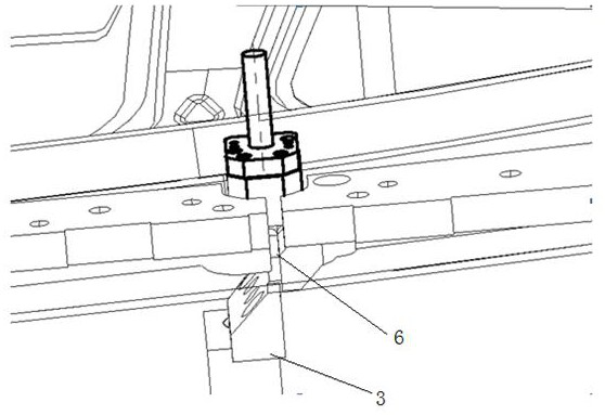
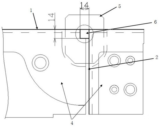
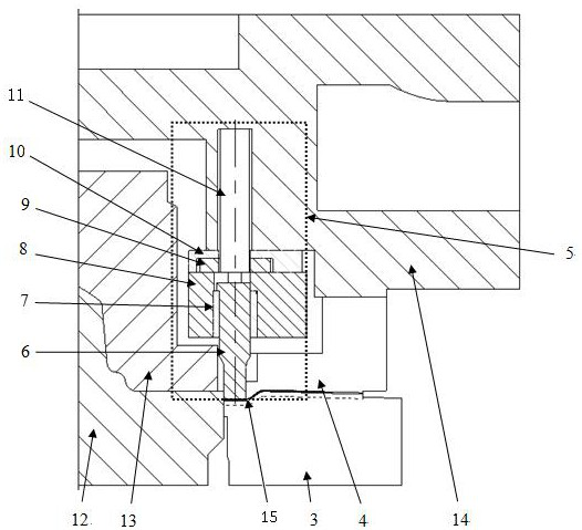
[0027] Such as figure 1 , 2 , shown in 3, the standardization movable scrap knife of the present invention is arranged on the trimming mold, and the trimming mold comprises a patrix 14 and a lower die seat, and the patrix 14 is provided with a patrix trimming knife 4, and the patrix trims The side knife 4 includes the main cutting edge 1 of the upper mold and the scrap cutting edge 2 of the upper mold. The lower mold base is provided with the scrap knife 3 of the lower mold. The key point is that the upper mold trimming knife 4 is also provided with a movable upper mold blade that can move up and down. 6 and the movable scrap knife assembly 5 that drives the movable upper mold edge 6; the movable scrap knife assembly 5 is embedded in the main edge 1 of the upper mold, so that the movable upper mold edge 6 is located on the main edge 1 of the upper mold and the waste cutting edge of the upper mold 2, and corresponds to the position of the waste knife 3 of the lower mold; the b...


PUM


Abstract

The invention provides a standard movable scrap knife arranged on a trimming mold. The trimming mold comprises an upper mold base and a lower mold base, wherein an upper trimming knife arranged on theupper mold base and comprises an upper mold primary cutting edge and an upper mold scrap cutting blade; and a lower mold scrape knife is arranged on the lower mold base. The key point of the standardmovable scrap knife is as follows: a movable upper mold blade capable of moving up and down and a movable scrap knife assembly which drives the upper mold blade are also arranged on the upper mold trimming knife; the movable scrap knife assembly is embedded into the upper mold primary cutting edge, so that the movable upper mold blade is located on a part where the upper mold primary cutting edgeand the upper mold scrap cutting blade join and corresponds to the position of the lower mold scrape knife; and the bottom of the movable upper mold blade is a flat molded surface. Scrap at the jointof the upper mold primary cutting edge and the upper mold scrap cutting blade is cut in a pressed state, so that trimming scrap iron is prevented from being generated as the scrap is torn.

Description

technical field [0001] The invention belongs to the field of stamping and forming of automobiles, in particular, the invention relates to a standardized movable scrap knife and trimming die structure. Background technique [0002] With the continuous development of the automobile industry, the quality requirements of automobile panels are getting higher and higher. During the production process of automobile panels, the waste knife in the trimming process will drop iron filings, and the iron filings will fall to the working surface of the mold, resulting in Defects such as pitting and pitting on the surface are a difficult problem faced by the stamping industry. [0003] When the main cutting edge of the traditional trimming die is cut, the pressing core of the plate part presses the sheet material, and the trimming of the main cutting edge is controllable. At the junction, scrap tearing is the main cause of filings. Contents of the invention [0004] The purpose of the ...

Claims


Application Information

Patent Timeline
Patent Type & Authority Patents(China)
IPC IPC(8): B21D28/14
CPCB21D28/14
Inventor 黄祥坤彭本栋
Owner CHERY AUTOMOBILE CO LTD
Why Eureka
Try Eureka