Distributed solar heat storage device

A heat storage device and heat storage technology, applied in the field of solar energy utilization, can solve the problems of increased investment cost, scale formation, low cost, etc., and achieve the effects of rapid cost reduction, small heat collection area, and rapid output increase

Pending Publication Date: 2018-07-20
于献榕
View PDF6 Cites 0 Cited by
  • Summary
  • Abstract
  • Description
  • Claims
  • Application Information

AI Technical Summary

Problems solved by technology

The main reason why it is difficult to commercialize solar-thermal power stations on a large scale is that trough-type solar-thermal power stations and tower-type solar-thermal power stations need to be built on a wide flat ground. The larger the scale, the lower the cost. For large-scale power station projects that rely on government investment, it is difficult to increase the output, and the low output in turn restricts the maturity of the industrial chain and the reduction of costs; although the dish-type photothermal power station is suitable for realizing distributed power stations, the manufacturing cost of the Stirling engine It is too high, it is difficult to reduce it to a level comparable to photovoltaics
[0003] The main disadvantages of domestic solar water heaters and commercial hot water systems are: (1) cannot actively track the sun, and the heat collection efficiency is not high enough; (2) long-term storage of water in water tanks and vacuum tubes will cause scaling; (3) when used in severe cold areas, There is a hidden danger of freezing and bursting; (4) It cannot generate electricity or steam, and the scope of application is not wide; (4) It is not good-looking
[0004] The main disadvantages of photovoltaic power plants are: (1) The photoelectric conversion efficiency is not high enough, and it will decay year by year; (2) When the technology of actively tracking the sun is not used, the heat collection efficiency is not high enough, but the investment cost will increase after adoption; (3) Cogeneration of heat and power cannot be realized, and the energy utilization rate is low; (4) It is easily affected by the weather, and the power generation is not stable; (5) The generated electricity must be transmitted to the grid immediately, and the grid needs to be dispatched, so the absorption capacity of the grid The requirements are very high, which is also one of the main reasons for "abandoning light and limiting electricity"

Method used


Image

  • Distributed solar heat storage device
  • Distributed solar heat storage device
  • Distributed solar heat storage device

Examples


Embodiment 1

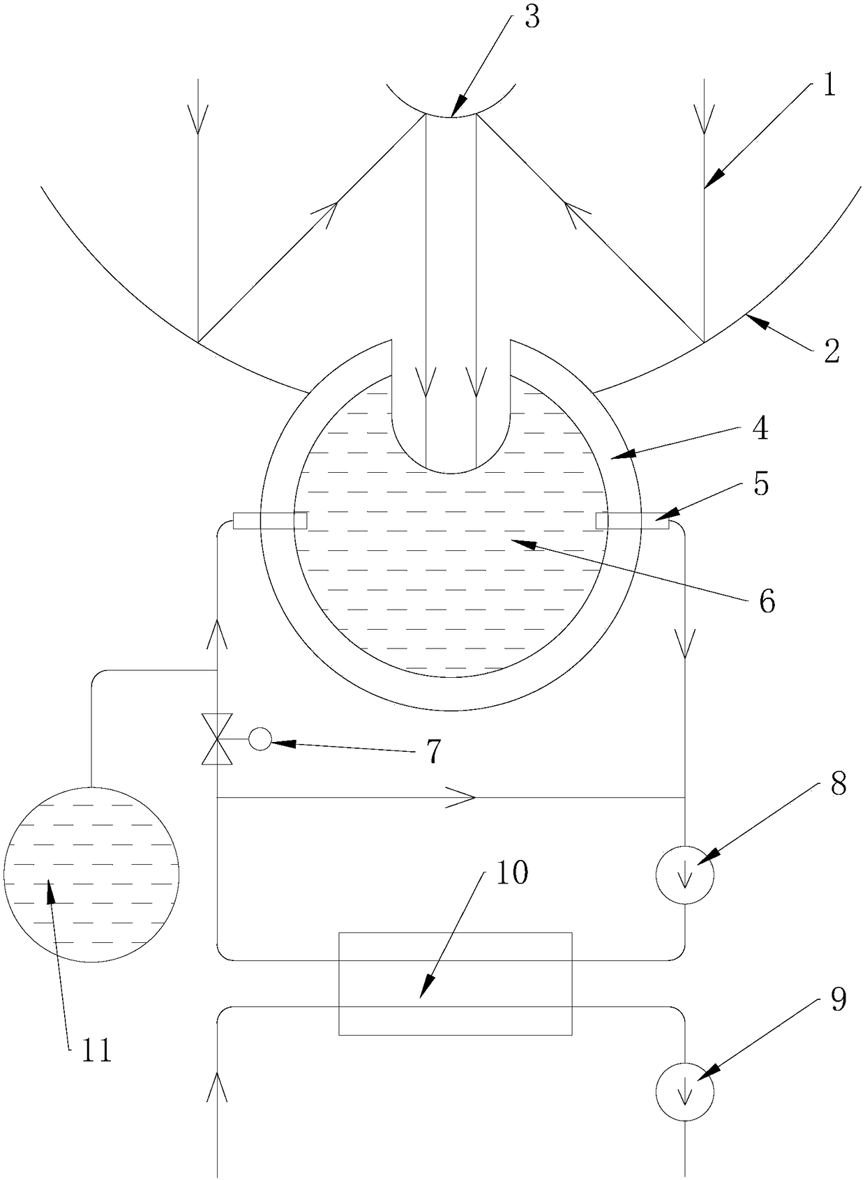
[0080] like figure 1 , 3 -8, the present embodiment consists of a light concentrating device, a heat storage container 12, a regulating valve 7, an oil pump 8, a water pump 9, a heat exchanger 10, an expansion tank 11, a cloud platform 18, a lower frame 21, and a support stand 22 , Pitch transmission mechanism and horizontal transmission mechanism;

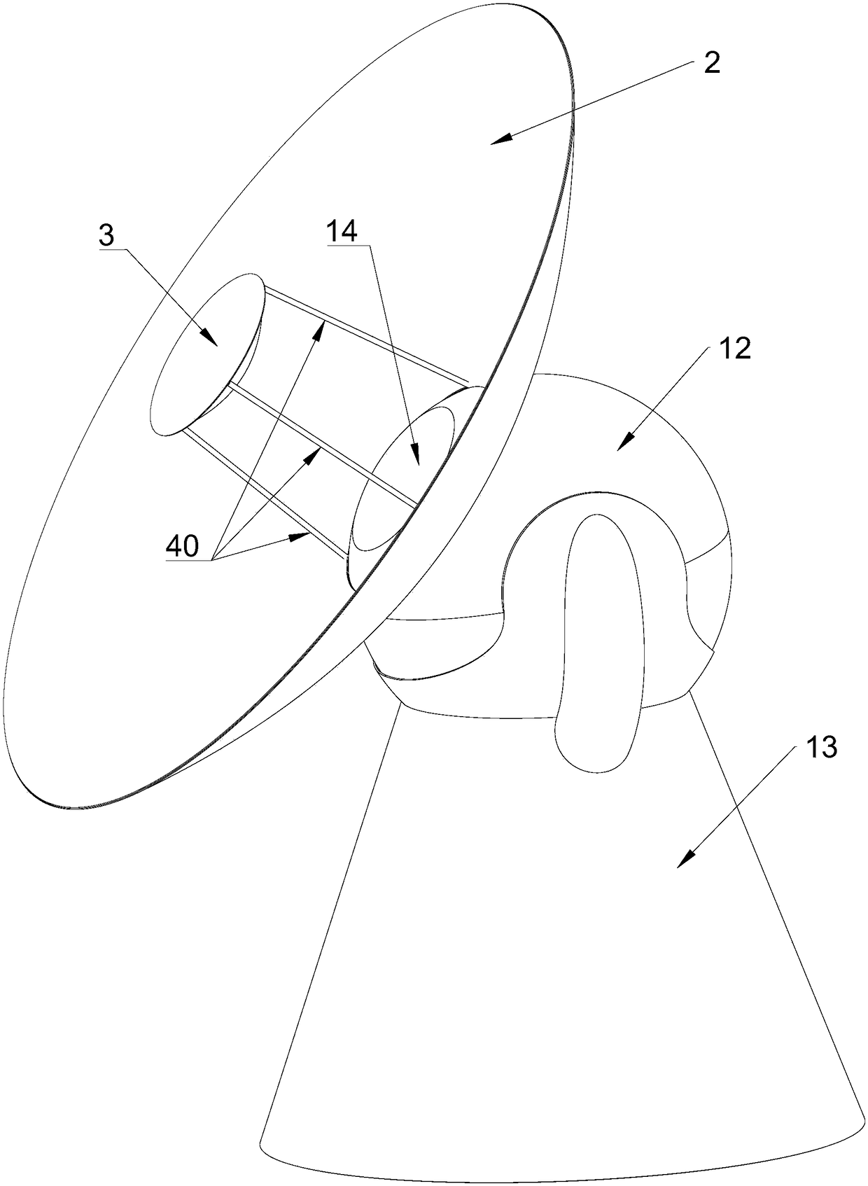
[0081] The light collecting device comprises a large reflector 2, a small reflector 3 and a pole 40, and the small reflector 3 is connected to the large reflector 2 through the pole 40; The electronic module composed of electronic gyroscope measures the azimuth angle of the concentrating device;

[0082] The light concentrating device is installed on the heat storage container 12; the heat storage container 12 is composed of an outer shell 23, an insulation layer 4, a heat storage container liner 25, a tempered glass 14 and a vacuum glass 24; the heater 26 is installed on the heat storage container liner 25 Above, the two form ...

Embodiment 2

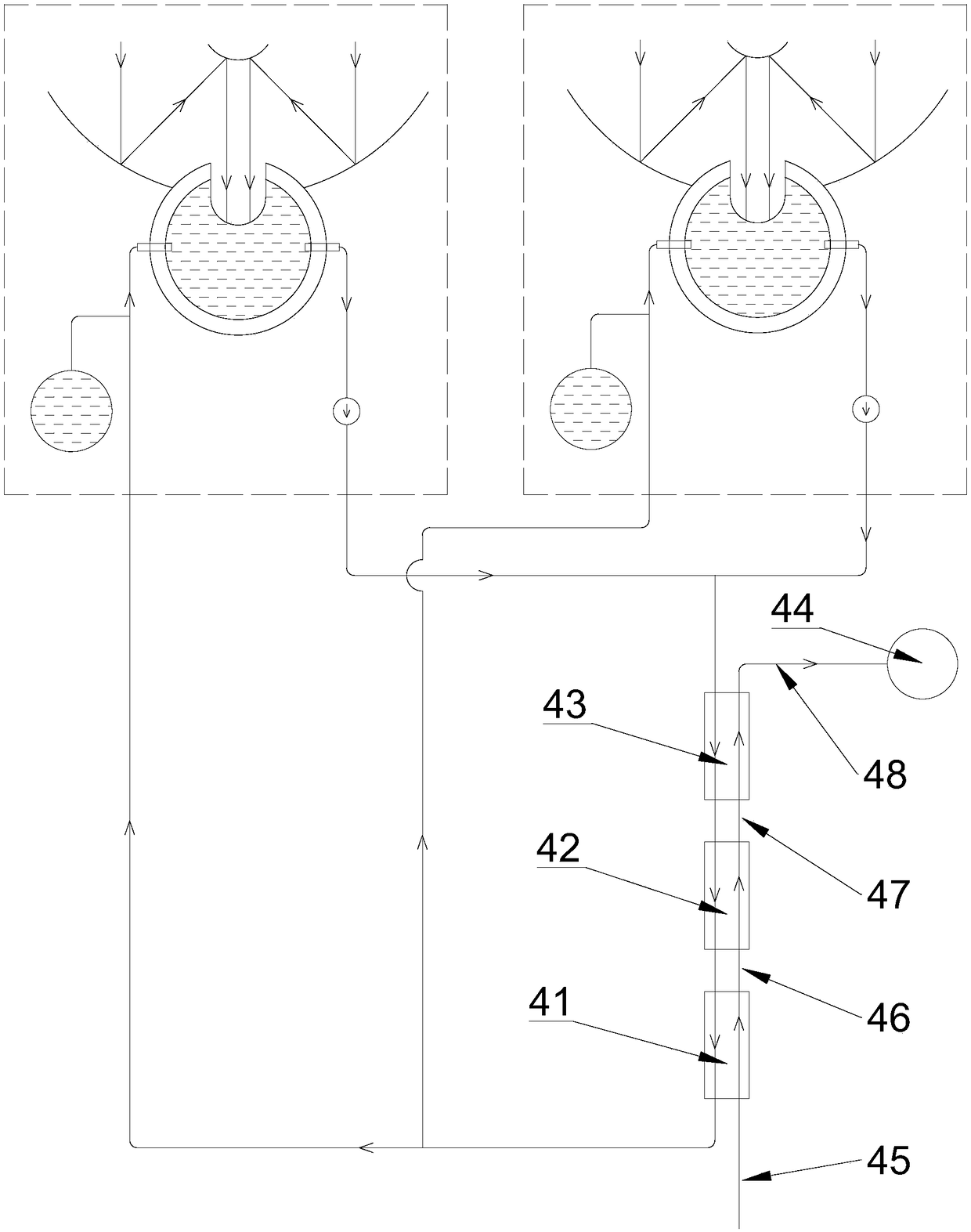
[0099] like Figure 2-6 , 8, and 9, the present embodiment is made up of light concentrating device, heat storage container 12, oil pump 8, expansion tank 11, cloud platform 18, lower frame 21, support stand 22, pitch transmission mechanism and horizontal transmission mechanism;

[0100] The light collecting device comprises a large mirror 2, a small mirror 3 and a pole 40, and the small mirror 3 is connected to the large mirror 2 through the pole 40; the back of the small mirror 3 is equipped with an electronic compass, a biaxial tilt sensor and An electronic module composed of electronic gyroscopes is used to measure the azimuth angle of the light-gathering device;

[0101] The light concentrating device is installed on the heat storage container 12; the heat storage container 12 is composed of an outer shell 23, an insulation layer 4, a heat storage container liner 25, a tempered glass 14 and a vacuum glass 24; the heater 26 is installed on the heat storage container liner ...

Embodiment 3

[0117] This embodiment is a design method using a vacuum insulation structure as the insulation layer 4 .

[0118] like figure 1 , 3 , 4, 6-8, and 10 show that the present embodiment consists of light concentrating device, heat storage container 12, regulating valve 7, oil pump 8, water pump 9, heat exchanger 10, expansion tank 11, cloud platform 18, lower frame 21. Supporting platform 22, pitch transmission mechanism and horizontal transmission mechanism;

[0119] The light-gathering device comprises a large reflector 2, a small reflector 3 and a strut 40, and the small reflector 3 is connected to the large reflector 2 through the strut 40;

[0120] The light concentrating device is installed on the heat storage container 12; the heat storage container 12 is made up of the shell 23, the heat storage container liner 25, the vacuum pressure-bearing shell 50, the tempered glass 14, the Dewar bottle 49 and the bearing member 55; the heater 26 and The load-bearing member 55 is ...


PUM


Abstract

The invention relates to a distributed solar heat storage device. A light-gathering device is composed of a large reflector 2 and a small reflector 3, has two degrees of freedom of pitch rotation andhorizontal rotation and can track a sun azimuth; the light-gathering device gathers sunlight onto a heat storage container 12 so as to heat heat-conducting oil 6 inside the heat storage container 12;the heat storage container 12 is wrapped with a heat-preservation layer 4, and thus the heat storage function is achieved; heat of the heat-conducting oil 6 is transmitted to tap water through a heatexchanger 10, and thus hot water can be produced; and the heat-conducting oil 6 of the multiple distributed solar heat storage devices is gathered to generate high-temperature steam 48, and thus a turbo generator set 44 can be driven to generate power. The whole device does not have complex technique and scarce materials, and is low in cost and suitable for quantity production; and the distributedsolar heat storage device can access to the consumer goods market and the industrial and commercial markets simultaneously only through an industry chain, the yield is increased more rapidly, the industry chain matures more rapidly, and the cost is reduced more rapidly.

Description

technical field [0001] The invention relates to the field of solar energy utilization, in particular to a distributed solar heat storage device. Background technique [0002] At present, there are two main methods of utilizing solar energy: producing hot water and generating electricity. The technical route of the former is mainly household solar water heaters and commercial hot water systems, while the technical route of the latter is mainly photovoltaic power plants and photothermal power plants. The most widely used technology routes are household solar water heaters, commercial hot water systems and photovoltaic power plants, while solar thermal power plants are still in the demonstration project stage as a whole, and it is still far away from large-scale commercialization. The main reason why it is difficult to commercialize solar-thermal power stations on a large scale is that trough-type solar-thermal power stations and tower-type solar-thermal power stations need to...

Claims


Application Information

Patent Timeline
Patent Type & Authority Applications(China)
IPC IPC(8): F24S23/70F24S60/30F24S50/20
CPCY02E10/47
Inventor 于献榕
Owner 于献榕
Why Eureka
Try Eureka