New Tail Valves for Pipe-in-Pipe Pipelines

A tail valve, a new type of technology, used in valve devices, control valves, safety valves, etc., can solve the problems of development obstacles, difficult design, and high construction costs, and achieve the effect of rapid liquid discharge and protection of external equipment.

Active Publication Date: 2021-07-23
陈奎宏
View PDF6 Cites 0 Cited by
  • Summary
  • Abstract
  • Description
  • Claims
  • Application Information

AI Technical Summary

Problems solved by technology

However, the layout of the three pipes has become a difficulty, causing problems such as difficult design, high construction cost, and large demand for pipeline raw materials, and the development has been hindered a bit.

Method used


Image

  • New Tail Valves for Pipe-in-Pipe Pipelines
  • New Tail Valves for Pipe-in-Pipe Pipelines
  • New Tail Valves for Pipe-in-Pipe Pipelines

Examples


Embodiment 1

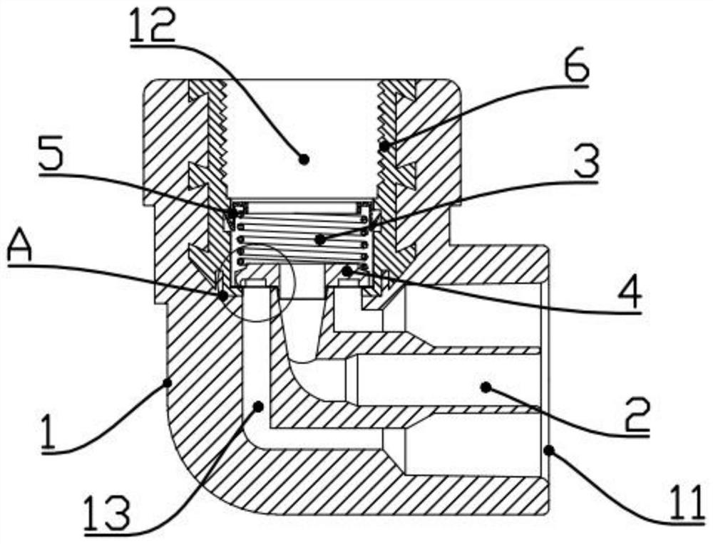
[0049] like Figure 1-4 As shown, a novel tail valve for a pipe-in-pipe pipeline includes a hollow tail valve body 1, and the tail valve body 1 is provided with a tail valve liquid inlet 11 for connecting a pipe-in-pipe and a In connection with the tail valve outlet 12 of the external equipment, the tail valve body 1 is coaxially provided with a corresponding tail valve inner pipe 2, and the tail valve inner pipe 2 is fixed on the tail valve through at least one tail valve connecting rib. Inside the tail valve body 1.

[0050] The liquid outlet end 12 of the tail valve is provided with an elastic member 3 and an elastic valve plate 4, the elastic member 3 is preferably a spring, and the middle part of the elastic valve plate 4 is provided with a liquid outlet hole 41 communicating with the inner pipe 2 of the tail valve, and the The elastic valve plate 4 is moved and sealed at the end of the return cavity 13 of the outer tube through the elastic member 3 .

[0051] Preferabl...

Embodiment 2

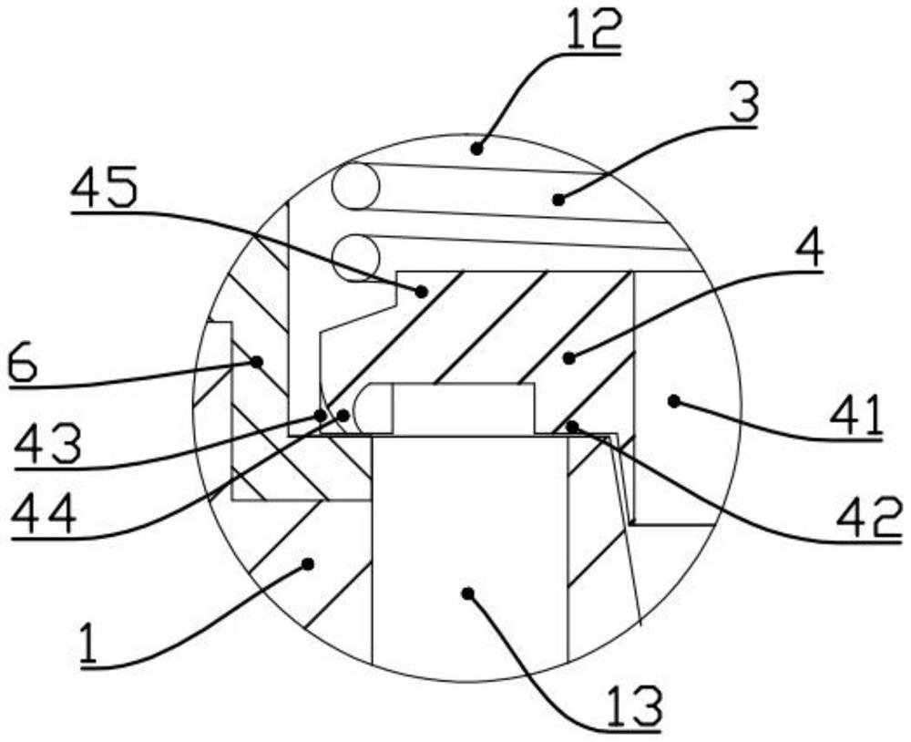
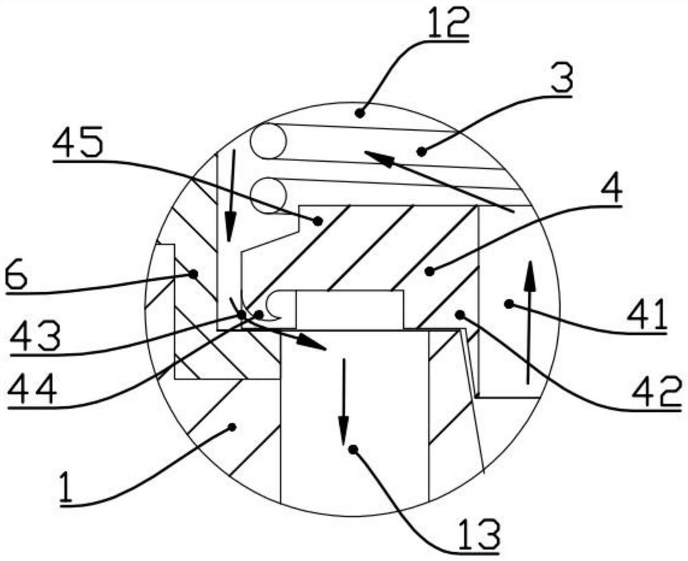
[0060] like Figure 5 , 6 As shown, the present embodiment is basically similar to the first embodiment, the difference is that when the outlet valve outlet 12 of the tail valve is under high pressure, the inner annular sealing part 42 is deformed and leads to the return cavity 13 of the outer tube to realize pressure relief.

[0061] Alternatively, the inner annular sealing portion 42 is provided with several pressure relief ribs A44 in the circumferential direction, and when the outlet valve outlet 12 of the tail valve is under high pressure, the pressure relief ribs A44 bend and lead to the return cavity 13 of the outer pipe.

Embodiment 3

[0063] like Figure 7 , 8 As shown, this embodiment is basically similar to Embodiment 1, and the difference is that the elastic valve plate 4 is provided with an air bag 46 inside. Through the outer tube return chamber 13. Its specific structure is that the inner side of the elastic valve plate 4 is arranged in the installation groove on the outer wall of the inner tube of the tail valve, and there is a gap between the outer side and the inner wall of the tail valve valve. The outer side is extruded and deformed and leads to the return cavity 13 of the outer tube, so as to realize pressure relief.


PUM


Abstract

The invention belongs to the technical field of valves and pipe fittings, and particularly refers to a new type of tail valve for pipe-in-pipe pipelines, which includes a tail valve body, and a corresponding tail valve inner pipe is coaxially arranged in the tail valve body, and the tail valve inner pipe It is fixed in the tail valve body by at least one tail valve connecting rib; the liquid outlet end of the tail valve is provided with an elastic piece and an elastic valve plate, and the middle part of the elastic valve plate is provided with a liquid outlet hole connected to the inner pipe of the tail valve, and the elastic valve plate passes through the elastic The active and sealed parts are arranged at the end of the return cavity of the outer tube. The present invention realizes two functions of the tail valve through different elastic valve structures, one of which is: when cold water enters the inner and outer pipes at the same time, the elastic valve is pushed open by force, and the liquid outlet of the tail valve is simultaneously discharged, realizing The second is: when the hot water enters the inner pipe of the tail valve, when the liquid outlet of the tail valve encounters high pressure, the elastic valve plate is deformed by force, and the return cavity of the outer pipe is connected to realize pressure relief backflow, thereby protecting the external equipment at the outlet end of the tail valve.

Description

technical field [0001] The invention belongs to the technical field of valves and pipe fittings, in particular to a novel tail valve used for pipe-in-pipe pipelines. Background technique [0002] In the field of hot water supply, the old-fashioned single pipe is generally used to supply hot water. It is popular with consumers because of its convenient installation and low cost, and it has gradually become the industry's installation specification and industry installation standard. However, when the single-pipe pipeline is relatively long, a large amount of cold water in the pipeline needs to be emptied before using hot water, resulting in a relatively long waiting time for hot water, and also causing a large amount of waste of water resources. [0003] With the continuous advancement of science and technology, the concept of hot water circulation pipelines has been introduced in the field of hot water supply. In the hot water circuit, hot water supply pipes, hot water retur...

Claims


Application Information

Patent Timeline
Patent Type & Authority Patents(China)
IPC IPC(8): F16K15/16F16K17/30
CPCF16K15/16F16K17/30
Inventor 陈友苗陈奎宏
Owner 陈奎宏
Why Eureka
Try Eureka