
Comb type mixing nozzle of injection molding machine

An injection molding machine and comb-type technology, which is applied in the field of comb-type mixing nozzles, can solve the problems of lower assembly efficiency, assembly trouble, and cost increase, and achieve the effects of improved assembly efficiency, convenient maintenance, and reduced manufacturing costs

Pending Publication Date: 2018-07-20
广东联升精密机械制造有限公司
View PDF8 Cites 0 Cited by
  • Summary
  • Abstract
  • Description
  • Claims
  • Application Information

AI Technical Summary

Problems solved by technology

The structure is complex and involves many parts, which leads to troublesome assembly and reduces assembly efficiency; in addition, when the mixing nozzle is clogged, it is difficult to maintain due to the complex structure. The method is to directly replace the mixing nozzle, resulting in cost Increase

Method used


Image

  • Comb type mixing nozzle of injection molding machine
  • Comb type mixing nozzle of injection molding machine
  • Comb type mixing nozzle of injection molding machine

Examples


no. 1 example

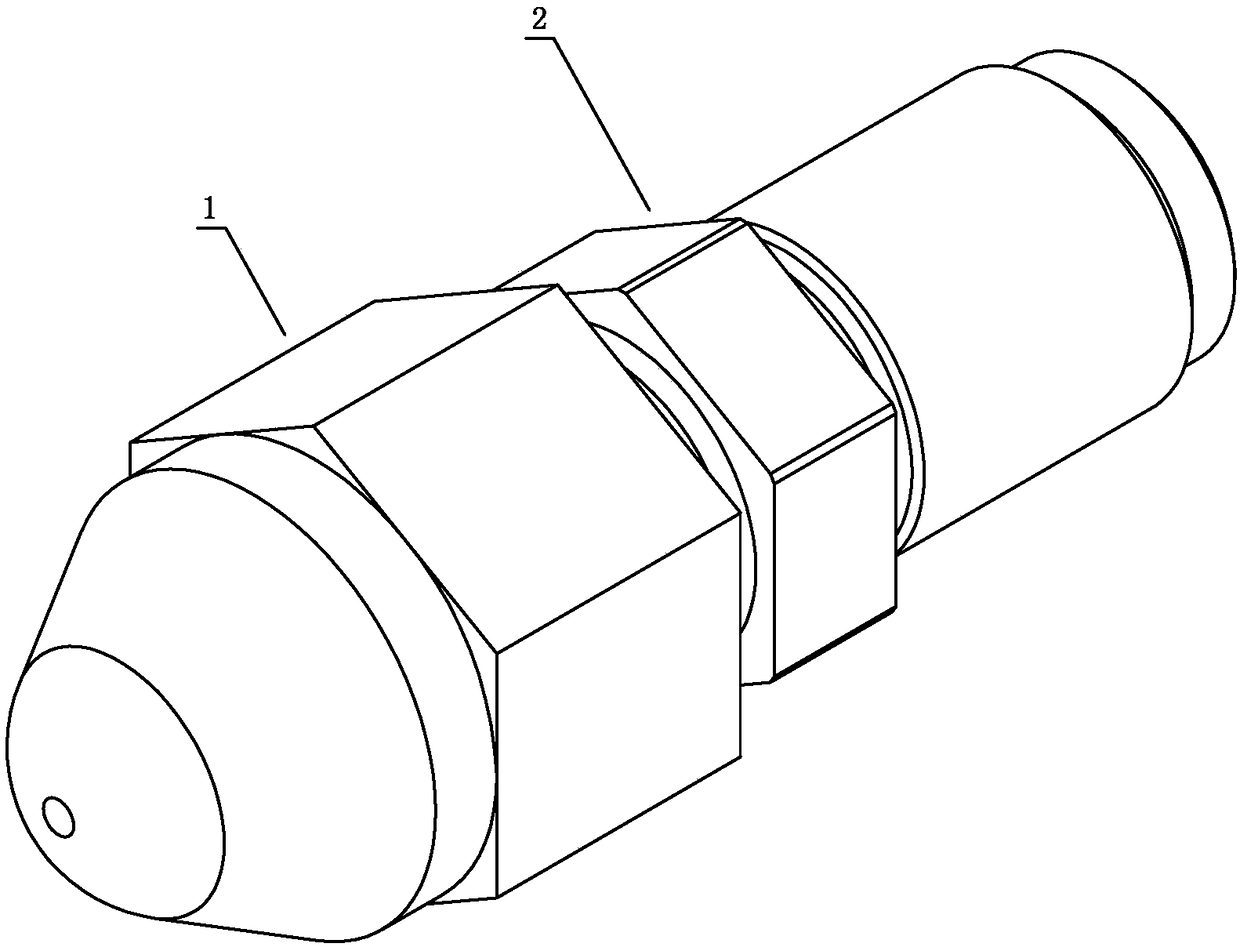
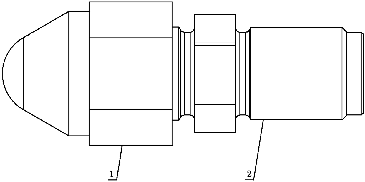
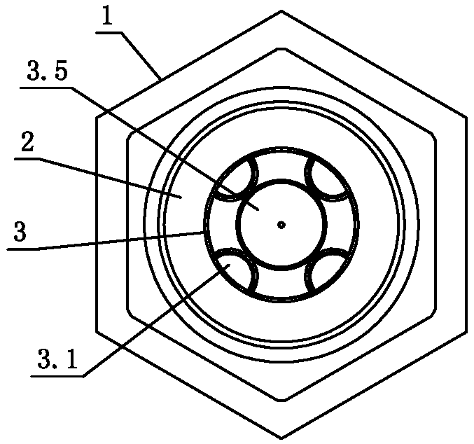
[0040] see Figure 1-Figure 21 The comb-shaped mixing nozzle of this injection molding machine includes a nozzle head 1 and a nozzle body 2 connected to each other. The inner cavity of the nozzle body 2 is provided with a comb-shaped mixing part 3. The comb-shaped mixing part 3 is a columnar body, and its surface There are two feed channels 3.1 and two discharge channels 3.4; one end of the feed channel 3.1 is closed and the other end is open, and it runs through to the feed end of the comb-shaped mixing part 3. The open end of the feed channel 3.1 is connected to the The inner cavity of the nozzle body 2 is directly connected; one end of the discharge channel 3.4 is closed and the other end is open, and it runs through to the discharge end of the comb-shaped mixing part 3, and the open end of the discharge channel 3.4 is directly connected to the inner cavity of the nozzle head 1 ; There is a glue comb structure between the feed channel 3.1 and the discharge channel 3.4, and ...

no. 2 example

[0048] see Figure 22-Figure 24 , the comb-shaped mixing nozzle of this injection molding machine is different from the first embodiment in that: the nozzle head 1 is a through structure, and its inner wall is provided with a second limiting boss 1.3, and the comb-shaped mixing part 3 is arranged on the nozzle head 1 The inner cavity, the second limiting boss 1.3 the discharge end of the comb-shaped mixing part 3; the outer wall of the nozzle head 1 is provided with the second external thread 1.4, the inner wall of the nozzle body 2 is provided with the second internal thread 2.4, the nozzle The body 2 and the nozzle head 1 are screwed to each other through the internal and external threads 2.3; the end of the nozzle head 1 is provided with a second connecting shaft 1.5, and the inner wall of the nozzle body 2 is provided with a second connection hole 2.5, when the nozzle body 2 and the nozzle head 1 are connected , the second connecting hole 2.5 and the second connecting shaf...


PUM


Abstract

The invention discloses a comb type mixing nozzle of an injection molding machine. The comb type mixing nozzle comprises a nozzle head and a nozzle body which are mutually connected. A comb type mixing component is arranged in the nozzle body, the comb type mixing component is in a cylindrical object, the surface of the comb type mixing component is provided with one or more feeding channels and one or more discharge channels, one end of each feeding channel is closed, the other end of each feeding channel is opened and penetrates to the feeding end of the comb type mixing component, the opened ends of the feeding channels communicate with an inner cavity of the nozzle body, one end of each discharge channel is closed, the other end of each discharge channel is opened and penetrates to thedischarge end of the comb type mixing component, the opened ends of the discharge channels communicate with an inner cavity of the nozzle head, a glue passing comb structure is arranged between the feeding channels and the discharge channels, and the feeding channels communicate with the discharge channels through the glue passing comb structure. The plasticizing and mixing effect of plastic meltis effectively improved, plastic materials are more uniform, and therefore the appearance quality and mechanical property of plastic products can be improved.

Description

technical field [0001] The invention relates to an injection molding machine, in particular to a comb-type mixing nozzle of the injection molding machine. Background technique [0002] Due to the rapid development of the plastics industry, the application fields of plastic products continue to expand, and it often occurs that the mixing effect of the traditional mixing nozzle cannot meet the requirements of certain products. In order to solve this situation, it is necessary to design a mixing effect with better mixing effect. Mouth. In order to solve the above problems, Chinese Patent Document No. CN201998382U disclosed a filter-type static mixing nozzle on October 5, 2011, specifically disclosing that it includes a mixing jacket with a channel inside, and is sealed and fixedly connected at one end of the mixing jacket. A joint, the other end of the mixing coat is sealed and fixedly connected to a nozzle, and several shearing and dispersing mixing nets are arranged in the m...

Claims


Application Information

Patent Timeline
Patent Type & Authority Applications(China)
IPC IPC(8): B29C45/20
CPCB29C45/20
Inventor 刘锦灿郭培星王少波
Owner 广东联升精密机械制造有限公司
Learn More