Material cutting device

A cutting device and material technology, applied in metal processing and other directions, can solve problems such as affecting the efficiency of cleaning and cutting, and difficult to clean, and achieve the effect of avoiding difficult cleaning and improving efficiency.

Pending Publication Date: 2018-07-20
SUZHOU ZHONGSU REPROCESSING MACHINERY
View PDF0 Cites 0 Cited by
  • Summary
  • Abstract
  • Description
  • Claims
  • Application Information

AI Technical Summary

Problems solved by technology

In the traditional cutting device, the blade is installed in the cutting cavity, which is not easy to clean after the material adheres, which seriously affects the efficiency of cleaning and cutting

Method used


Image

  • Material cutting device
  • Material cutting device
  • Material cutting device

Examples


Embodiment Construction

[0016] The technical solution of the present invention will be further described below in conjunction with the accompanying drawings.

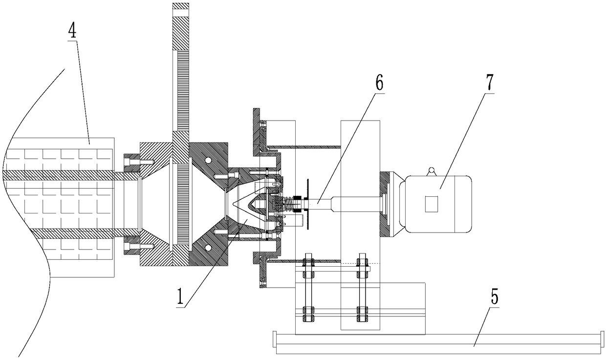
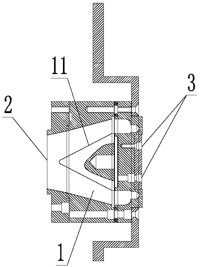
[0017] see Figure 1-3 As shown, the above-mentioned material cutting device includes a frame (not shown in the figure), a material cutting chamber 1 arranged on the frame, a feed port 2 provided at one end of the material cutting chamber 1, and a material cutting chamber provided at one end of the material cutting chamber. 1 The discharge port 3 at the other end, the conveying mechanism 4 for feeding the material into the material cutting chamber 1 through the feed port 2. In this embodiment, the discharge port 3 is ring-shaped, and the material cutting chamber 1 is provided with a guide member 11 for guiding the material from the feed port 2 to the discharge port 3. The guide member 11 is conical, and the cone angle is located at the inlet On the side of the material opening 2, the guide member 11 is distributed coaxially with the material ...


PUM


Abstract

The invention discloses a material cutting device. The material cutting device comprises a rack, a material cutting cavity, a feeding opening, a discharging opening, a delivery mechanism and a cuttingmechanism, wherein the material cutting cavity is formed in the rack; the feeding opening is formed in one end of the material cutting cavity; the discharging opening is formed in the other end of the material cutting cavity; the delivery mechanism is used for delivering materials into the material cutting cavity through the feeding opening; and the cutting mechanism is used for cutting the materials in the material cutting cavity. The cutting mechanism comprises a sliding table, a rotating shaft, a driving mechanism and a blade, wherein the sliding table is arranged on the rack in a slidingmanner in the direction of being close to or away from the material cutting cavity; the rotating shaft is arranged on the sliding table in a manner that the rotating shaft rotates around the axis of the rotating shaft; the driving mechanism is arranged on the sliding table and used for driving the rotating shaft to rotate; and the blade is arranged at one end of the rotating shaft and used for extending into the material cutting cavity through the discharging opening. According to the material cutting device, the blade is movably arranged outside the material cutting cavity; when the materialcutting device is used, the blade is extended into the material cutting cavity through the sliding table to cut the materials; the problem that after the materials adhere to the blade, the blade is not easy to clean can be effectively avoided; and cleaning efficiency and cutting efficiency are improved.

Description

technical field [0001] The invention relates to a material cutting device. Background technique [0002] After the material is stirred and cut by the blade at high speed, it is output from the discharge port. Some materials (such as plastic) have a certain viscosity after friction and heat up, and are easy to stick between the blade and the discharge port. In the traditional cutting device, the blade is installed in the cutting cavity, which is not easy to clean after the material adheres, which seriously affects the efficiency of cleaning and cutting. Contents of the invention [0003] The object of the present invention is to provide a material cutting device, the blade is easy to clean, and the cutting efficiency is high. [0004] In order to achieve the above object, the technical scheme adopted in the present invention is: [0005] A material cutting device, comprising a frame, a material cutting cavity arranged on the frame, a feed opening set at one end of the m...

Claims


Application Information

Patent Timeline
IPC IPC(8): B26D1/25B26D7/26
CPCB26D1/25B26D7/2614
Inventor 王卫康
Owner SUZHOU ZHONGSU REPROCESSING MACHINERY
Why Eureka
Try Eureka