
Sheet curling device

A curling device and sheet technology, which is applied in the direction of feeding device, positioning device, storage device, etc., can solve the problems of wasting time, wasting labor resources, and not easy to bend the sheet, achieving good results, avoiding sheet adhesion, and easy rolling edge effect

Active Publication Date: 2019-03-15
JIANGSU QINGGONG COMPOSITE TECH CO LTD
View PDF4 Cites 0 Cited by
  • Summary
  • Abstract
  • Description
  • Claims
  • Application Information

AI Technical Summary

Problems solved by technology

However, in actual operation, due to the low plasticity of the aluminum plate with high strength, it is not easy to bend the plate directly by using pressure. It is often necessary to manually heat the part to be curled, and then use the bending punch to press down, not only Waste of labor resources and waste of time

Method used


Image

  • Sheet curling device
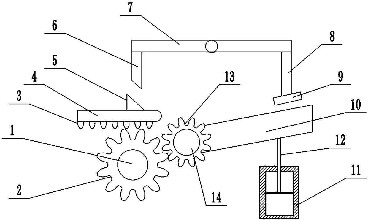
  • Sheet curling device

Examples


Embodiment Construction

[0021] The following is further described in detail through specific implementation methods:

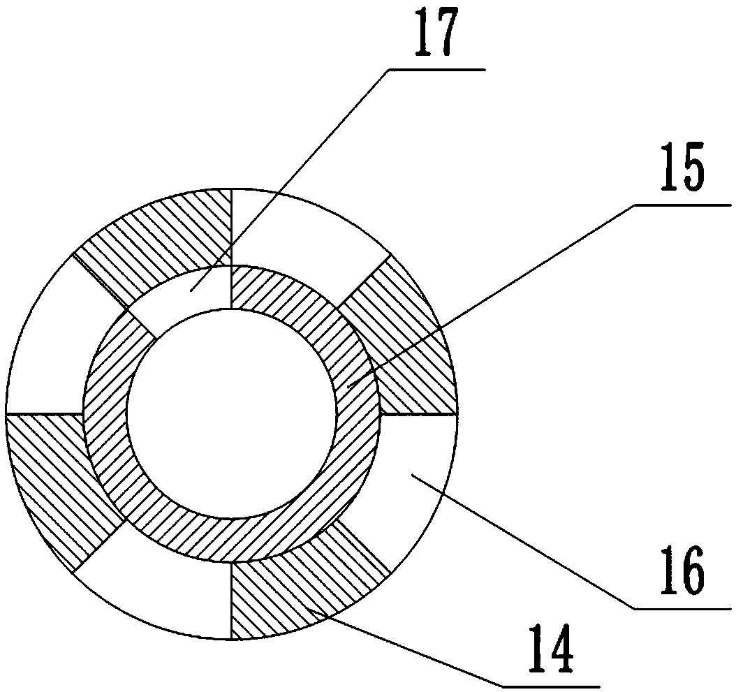
[0022] The reference signs in the drawings of the description include: rotating shaft 1, first gear 2, rack 3, bending punch 4, wedge 5, wedge bar 6, cross bar 7, pressing bar 8, pressing plate 9, supporting plate 10 , Piston barrel 11, piston rod 12, second gear 13, outer cylinder 14, inner cylinder 15, first through hole 16, second through hole 17.

[0023] like figure 1 As shown, the plate hemming device includes a frame, and the frame is provided with a bending part, a fixing part and a driving part. The bending part includes a bending punch 4 that is slidably connected to the frame horizontally. The right end is semicircular, and the upper surface of the bending punch 4 is fixed with a wedge 5 with a wedge surface facing the upper right, and the lower surface of the bending punch 4 is connected with a rack 3 .

[0024] The driving part is located below the bending punch 4. The...


PUM


Abstract

The invention belongs to the field of decoration engineering and particularly discloses a plate crimping device. A fixing portion comprises a support plate and a pressing plate, wherein the pressing plate is located above the support plate. A bending portion comprises a bending punch, wherein the bending punch is located at one side of the support plate. A wedge block is connected to the upper surface of the bending punch. A wedge rod is connected to a rack in a sliding manner. A cross bar is connected between the wedge rod and the pressing plate and hinged to the rack. A gear rack is connected to the lower surface of the bending punch. A driving portion comprises a rotating shaft. A first gear is arranged on the rotating shaft. The fixing portion further comprises an outer barrel and an inner barrel, wherein the inner barrel is located inside the outer barrel. A second gear is arranged on the outer barrel. Multiple first through holes are formed in the side wall of the outer barrel. Asecond through hole is formed in the upper side of the inner barrel. The support plate is hinged to the rack. A piston barrel is arranged below the support plate. A piston is connected into the piston barrel in a sliding manner. A piston rod is fixed to the upper side of the piston. The rack is further provided with a vortex tube and a compressed air supply chamber. By means of the plate crimpingdevice, the requirement that a plate is heated in an automated manner in the plate crimping process is met.

Description

technical field [0001] The invention belongs to the field of decoration engineering, and in particular relates to a board curling device. Background technique [0002] In the manufacturing process of aluminum plate ornaments such as aluminum alloy doors and windows or aluminum-clad wood doors and windows, the curling processing of aluminum plates is involved. Usually, the curling of the aluminum plate is done by manual beating, which is time-consuming and labor-intensive. [0003] In order to solve the above problems, the sheet curling device in the prior art includes a frame, a support plate for fixing the sheet and a pressing plate above the support plate are arranged on the frame, and a folding joint is slidably connected to one side of the support plate on the frame. The bending punch, when in use, slides the bending punch towards the direction close to the support plate, and presses down the plate fixed on the support plate to realize curling. However, in actual opera...

Claims


Application Information

Patent Timeline
Patent Type & Authority Patents(China)
IPC IPC(8): B21D19/12B21D37/16B21D43/00
CPCB21D19/12B21D37/16B21D43/003
Inventor 熊顺斌
Owner JIANGSU QINGGONG COMPOSITE TECH CO LTD
Learn More