
Constant-current output circuit for improving power factor correction efficiency and power supply

A technology for improving power and constant current output, applied in the field of power supply, can solve the problems of increasing the volume of the power supply, low efficiency of the whole machine, large PFC loss, etc., and achieve the effect of reducing internal loss, simple structure and improving efficiency

Active Publication Date: 2018-07-10
SHENZHEN SOSEN ELECTRONICS CO LTD
View PDF5 Cites 1 Cited by
  • Summary
  • Abstract
  • Description
  • Claims
  • Application Information

AI Technical Summary

Problems solved by technology

[0003] According to the traditional circuit design, to obtain high power factor can be achieved by setting a power factor correction circuit (PFC circuit) in the drive power supply, but for low voltage input, the PFC loss of the above power factor correction circuit is very large, at this time, It is necessary to increase the power device and increase the heat sink to reduce the PFC loss, which not only increases the volume of the power supply, but also increases the cost and the efficiency of the whole machine is also low, which is not conducive to the purpose of green energy saving of LED products

Method used


Image

  • Constant-current output circuit for improving power factor correction efficiency and power supply
  • Constant-current output circuit for improving power factor correction efficiency and power supply
  • Constant-current output circuit for improving power factor correction efficiency and power supply

Examples


Embodiment Construction

[0042] In order to have a clearer understanding of the technical features, objectives and effects of the present invention, the specific embodiments of the present invention will now be described in detail with reference to the accompanying drawings.

[0043] In order to solve the technical problem, the embodiment of the present invention constructs a constant current output circuit that improves the efficiency of power factor correction. The constant current output circuit does not need to increase the power device, does not need to increase the heat sink, that is, it can be input at low voltage (low At the preset value), the real-time output voltage adjustment signal controls the PFC circuit to quickly adjust its output voltage according to the change of the input voltage, so that the peak current of the internal components of the PFC circuit is greatly reduced, so as to achieve the purpose of reducing the loss of the PFC circuit. Improve the power factor correction efficiency o...


PUM


Abstract

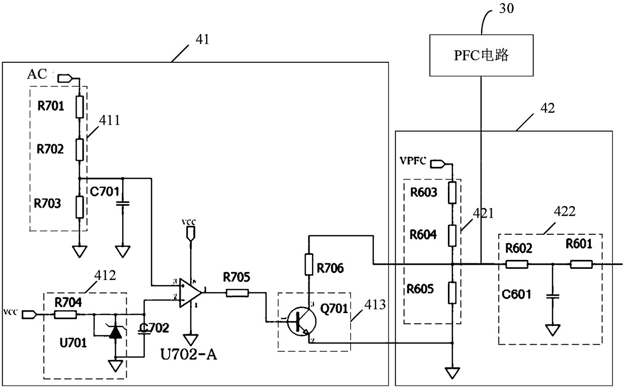
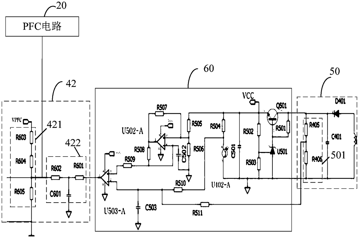
The invention relates to a constant-current output circuit for improving power factor correction efficiency and a power supply. The constant-current output circuit comprises a rectification circuit, aPFC circuit, a half-bridge resonant circuit and a detection control circuit, wherein the rectification circuit is connected with a mains supply and is used for receiving an alternating current and rectifying the alternating current to a DC voltage, the PFC circuit is connected with the rectification circuit and is used for receiving and correcting the DC voltage and outputting a PFC voltage, thehalf-bridge resonant circuit is connected with the PFC circuit and is used for receiving the PFC voltage and outputting an output voltage according to the PFC circuit, the detection control circuit isconnected with an input end of the rectification circuit and a control end of the PFC circuit, the detection control circuit is used for outputting a voltage adjustment signal to the control end of the PFC circuit when the mains supply is lower than a preset value, and the PFC circuit is used for receiving the voltage adjusting signal and reducing an output voltage of the PFC circuit according tothe voltage adjustment signal. The output voltage of the PFC circuit can be rapidly reduced when the input voltage of the mains supply is lower than the preset value, the internal loss of the PFC circuit is reduced, and the efficiency of the PFC circuit is improved.

Description

Technical field [0001] The present invention relates to the technical field of power supplies, and more specifically, to a constant current output circuit and a power supply that improve the efficiency of power factor correction. Background technique [0002] LED light source has the characteristics of high efficiency, energy saving, environmental protection, long life, easy maintenance, etc., and is widely used in various fields such as tone green lighting and indoor and outdoor lighting. Based on the characteristics of the LED light source itself, it must be powered by a constant current source. Therefore, there is a demand for high-efficiency constant current drive power LED applications. [0003] According to the traditional circuit design, high power factor can be achieved by installing a power factor correction circuit (PFC circuit) in the driving power supply. However, for low voltage input, the PFC loss of the above power factor correction circuit is very large. At this tim...

Claims


Application Information

Patent Timeline
IPC IPC(8): H02M1/42
CPCH02M1/4233H02M1/4241H02M1/0054Y02B70/10
Inventor 王宗友邹超洋莫永福汤波兵
Owner SHENZHEN SOSEN ELECTRONICS CO LTD
Learn More