Double hook automatic hoisting structure and hoisting method

A hoisting and automatic technology, applied in the directions of traveling mechanism, transportation and packaging, load hoisting elements, etc., can solve the problems of large swing, inability to automatically hook the mold, and inability to realize automatic hoisting operations, to ensure safety and stability. Effect

Inactive Publication Date: 2018-07-10
ZHEJIANG SHUANGLIN PLASTIC MACHINERY
View PDF7 Cites 1 Cited by
  • Summary
  • Abstract
  • Description
  • Claims
  • Application Information

AI Technical Summary

Problems solved by technology

Its disadvantages: First, the hook of the factory crane is a steel rope type soft hook, which cannot be automatically hooked during the mold hooking process, and can only be hooked manually; second, the hook of the factory crane is a steel rope type soft hook. During the hoisting operation, the swing is large and the position between each station cannot be precisely controlled; the third is that the factory’s driving operation control mode is manual operation, which cannot realize automatic hoisting operations

Method used


Image

  • Double hook automatic hoisting structure and hoisting method

Examples


Embodiment 1

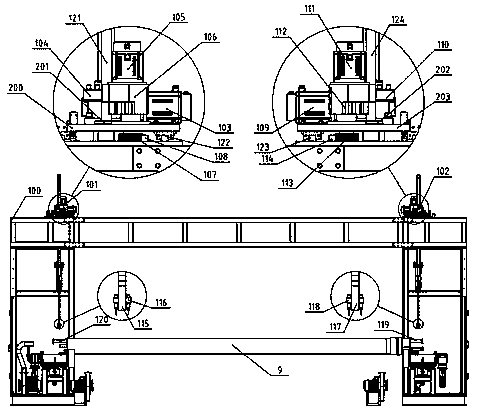
[0009] Embodiment 1: with reference to attached figure 1 . A double-hook automatic hoisting structure, including a PLC controller, is composed of a mobile crane frame 100, a left crane 101, and a right crane 102; the left crane 101 and the right crane 102 are installed on the mobile crane frame 100 Both ends and the left crane 101 and the right crane 102 are synchronously raised or lowered under the control of PLC. The left crane 101 is composed of a hook 115, a lift 104, a servo motor 103, a guide shaft 121, a sliding bearing 201, a detection switch 116, a servo motor 105, a reducer 106, a transmission gear 107, a rack 108, a guide rail 122, and a plate 200. . The rack 108 and two guide rails 122 are fixed on the crane frame 100, the plate 200 is fixed on the slide block of the guide rail 122, the reducer 106 is fixed on the plate 200 and the servo motor 105 is connected with the reducer 106, and the transmission gear 107 is fixed On the output shaft of the speed reducer 1...

Embodiment 2

[0010] Embodiment 2: On the basis of Embodiment 1, a hoisting method of a double-hook automatic hoisting structure, the left and right cranes 101 and 102 lift up and down, and the lifters 104 and 110 are driven by servo motors 103 and 109 to lift up and down the hooks 115 and 116 When lifting, it is guided by two or more guide shafts 121 and 124 to prevent the hook from swinging. When hoisting, the hooks 115 and 117 of the left crane 101 and the right crane 102 are equipped with two detection switches 116 and 118. , when the mold is lifted by hooks 115 and 117, 9 pairs of left boom 120 and right boom 119 are detected, and the lifting position is checked. If the position is inconsistent with the detection, the crane cannot lift; if the position is consistent with the detection , The lifting of the left crane 101 and the right crane 102 is controlled synchronously in position, so that the hoisted mold can be lifted and lowered smoothly. The left crane 101 is driven by the servo ...


PUM


Abstract

The invention relates to a double hook automatic hoisting structure and a hoisting method, and a front and back movement position, a lifting position and a hoisting position of each station are determined by a servo control system at a winding forming station, a cooling setting station and a demolding station in a composite pressure pipe production line so as to conduct precise hoisting. The hoisting structure includes a PLC, a moving crane rack, a left crane and a right crane; the left crane and the right crane are installed at the two ends of the moving crane rack, and the left crane and theright crane move up or down synchronously under the control of the PLC. The hoisting structure has the advantages that firstly, hook lifting guide shafts are used for guiding design to avoid the swing phenomenon of left and right lifting hooks during the lifting process, the synchronous control of lifting positions of the left and right lifting hooks is achieved in hoisting, and the stationarityof a hoisted mould in the lifting is ensured; secondly, hoisting rods are detected by detector switches on the lifting hooks, so that the safety of the hoisting is ensured.

Description

technical field [0001] The invention relates to a system for precise hoisting of the winding forming station, cooling and shaping station, and demoulding station in a composite pressure pipe production line. The invention discloses a double-hook automatic hoisting structure and a hoisting method, which belong to the field of manufacturing special hoisting structures. Background technique [0002] In the existing composite pressure pipe production line, the hoisting mode of the winding forming station, cooling and shaping station, and demoulding station adopts the factory driving hoisting method. Its disadvantages: First, the hook of the factory crane is a steel rope type soft hook, which cannot be automatically hooked during the mold hooking process, and can only be hooked manually; second, the hook of the factory crane is a steel rope type soft hook. During the hoisting operation, the swing is large and the position between each station cannot be precisely controlled; the ...

Claims


Application Information

Patent Timeline
Patent Type & Authority Applications(China)
IPC IPC(8): B66C13/22B66C13/48B66C13/46B66C13/06B66C9/14B66C17/06
CPCB66C13/22B66C9/14B66C13/06B66C13/46B66C13/48B66C17/06
Inventor 施经东刘勇周建国万本成
Owner ZHEJIANG SHUANGLIN PLASTIC MACHINERY
Why Eureka
Try Eureka