Robot for cutting wood plate

A robot and wood board technology, applied in the field of robots, can solve the problems of hanging hands, cutting irregular cutting positions, and reducing work efficiency, and achieves the effect of preventing random flying, ensuring safety, and ensuring cleanliness.

Pending Publication Date: 2018-07-10
KUNMING UNIV OF SCI & TECH
View PDF9 Cites 6 Cited by
  • Summary
  • Abstract
  • Description
  • Claims
  • Application Information

AI Technical Summary

Problems solved by technology

The existing wood cutting machine for wood processing is provided with grinding rollers on the upper side of the seven knives, so that the surface of the cut wood is smooth, so that the quality of the wood is improved, but the grinding on the wood cutting machine in the prior art The roller cannot be adjusted up and down. When processing and cutting wood boards of different thicknesses, the cutting effect is not good. During the cutting process, the staff hold the wood board with their hands, which will be more inconvenient and may cause the cutting wheel to hang on the hand, which will cause staff injuries. , and press the cut wood with the hand, the wood shakes due to the force of the cutting knife, at this time the hand cannot press the wood tightly, resulting in irregular cutting or changing the cutting position, which will cause waste of resources, and during the cutting process, There will be a lot of burrs on the cutting part of the wood board, which needs to be removed manually for polishing, which is a serious waste of time and reduces work efficiency

Method used


Image

  • Robot for cutting wood plate
  • Robot for cutting wood plate
  • Robot for cutting wood plate

Examples


Embodiment 1

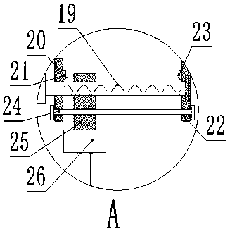
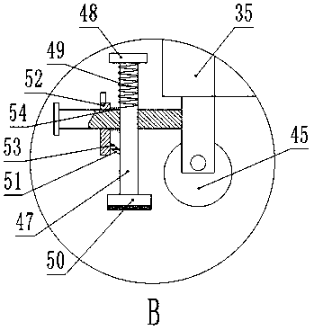
[0017] Embodiment 1: as Figure 1-5As shown, a robot for cutting wooden boards includes a workbench 1, on which a cutting hole 2 is arranged, and positioning rods 3 are fixed at the four corners of the top edge of the workbench 1, and the top of the positioning rod 3 A support bar A4 is fixedly provided, and a fixed vertical bar A5 is fixedly provided on the top surface of the support bar A4, and a support bar B6 is fixedly arranged between the two fixed vertical bars A5, and the center of the bottom surface of the support bar B6 A swing rod 8 is fixedly provided, and a sliding rod A9 and a connecting rod 14 are respectively hinged at the edge of the top surface and the bottom surface of the swing rod 8, and the top end of the sliding rod A9 is fixedly connected to the limit plate 10 through the support cross bar B6 A hydraulic telescopic rod 11 and a sleeve B28 are hinged at the edge of the top and bottom surfaces on the other side of the swing rod 8, the hydraulic telescopic...


PUM


Abstract

The invention relates to a robot for cutting a wood plate. The robot comprises a working table, which is provided with a cutting hole, wherein positioning rods are fixedly arranged at four corners ofthe edge of the top end of the working table, the top end of the positioning rod is fixedly provided with a support horizontal rod A, the top surface of the support horizontal rod A is fixedly provided with a fixed vertical rod A, a support horizontal rod B is fixedly arranged between the two fixed vertical rods A, the center position of the bottom surface of the support horizontal rod B is fixedly provided with a swinging rod, and the edge positions on the top surface and the bottom surface of one side of the swinging rod are respectively hinged to a sliding rod A and a connection rod. According to the present invention, through the hydraulic stretching rod, the swinging rod is controlled to freely swing back and forth, the cutting wheel and the burnishing wheel are controlled to operate,and the positions of the cutting wheel and the burnishing wheel can be adjusted according to the thickness of the wood plate, such that the wood plates with different thicknesses can be convenientlycut or burnished; and through the opposite clamping device and hand-operated wire pulling wire, the manual operation on the wood plate by the worker is not required so as to effectively ensure the work safety and the cutting stability.

Description

technical field [0001] The invention relates to a robot for cutting wood boards, which belongs to the technical field of robots. Background technique [0002] Board cutting is a very important link in wood processing, and it is an indispensable process in most wood processing. The existing wood cutting machine for wood processing is provided with grinding rollers on the upper side of the seven knives, so that the surface of the cut wood is smooth, so that the quality of the wood is improved, but the grinding on the wood cutting machine in the prior art The roller cannot be adjusted up and down. When processing and cutting wood boards of different thicknesses, the cutting effect is not good. During the cutting process, the staff hold the wood board with their hands, which will be more inconvenient and may cause the cutting wheel to hang on the hand, which will cause staff injuries. , and press the cut wood with the hand, the wood shakes due to the force of the cutting knife,...

Claims


Application Information

Patent Timeline
Patent Type & Authority Applications(China)
IPC IPC(8): B27C5/00B24B19/24B27G3/00
CPCB24B19/24B27C5/00B27G3/00
Inventor 龙华周金傲邵玉斌杜庆治
Owner KUNMING UNIV OF SCI & TECH
Why Eureka
Try Eureka