


Quick Research
Generate reliable direction feasibility study reports for your R&D in just a few steps.

Technical Q&A
Discover and master advanced knowledge NOW. Basics, ideas, possibilities, all at once.

Find Solutions
As an expert in R&D theories, this can generate solutions to your technical problems instantly.

Evaluate Feasibility
Analyze your overall solution with one click, know your potential R&D risks in advance.

Monitor Landscape
Get weekly tech updates, stay abreast of the latest tech innovations and key insights.
Non-overlapping winding tooth slot type dual-rotor permanent magnet synchronous motor
A permanent magnet synchronous motor, dual rotor technology, applied in the shape/style/structure of winding conductors, magnetic circuits, electrical components, etc., can solve the problems of low winding distribution coefficient and low power density, etc., to improve the winding coefficient, improve the Power factor, the effect of easy maintenance
- Summary
- Abstract
- Description
- Claims
- Application Information
AI Technical Summary
Problems solved by technology
Method used
Image


Examples
Embodiment 1
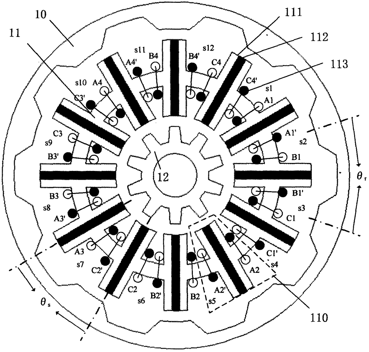
[0062] see figure 1 , the non-overlapping winding cogging type double-rotor permanent magnet synchronous motor of the present invention adopts a class winding,
[0063]
[0064] In this embodiment, m=3, t=0, k=1, n=4, and the sign is positive, so the pole distance ratio θ s / θ r Set at 5 / 6, which is 10 / 12. Wherein, m is the phase number of the motor, k is the logarithm of the same-phase armature winding 113 in each motor unit, and n is the number of motor units.
[0065] The non-overlapping winding cogging type double-rotor permanent magnet synchronous motor of the present invention includes a stator 11, an inner 10 and an outer rotor 12 respectively placed on the inner and outer sides of the stator 11, and the stator 11 and the inner and outer rotors are salient pole structures; There is an air gap between the stator 11 and the inner and outer rotors. The stator 11 includes several basic units 110 connected end to end. The basic unit 110 includes two half-H-shaped magn...
Embodiment 2
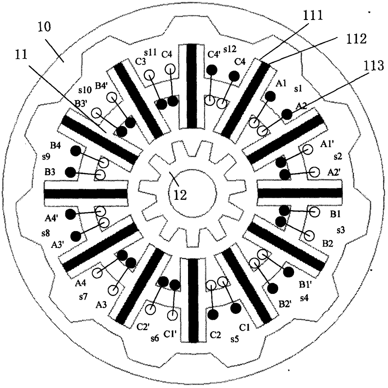
[0070] image 3 It is also a non-overlapping winding cogging type double-rotor permanent magnet synchronous motor. The difference between this embodiment and Embodiment 1 is that this embodiment uses a B-type winding,
[0071]
[0072] In this embodiment, m=3, t=0, k=4, n=1, and the sign is negative, so the pole distance ratio θ s / θ r Set for 11 / 12, which is 11 / 12. Wherein, m is the phase number of the motor, k is the logarithm of the same-phase armature winding 113 in each motor unit, and n is the number of motor units.
[0073] In this embodiment, the winding directions of the armature windings 113 belonging to two adjacent basic units 110 on the same stator yoke are the same; m=3 is an odd phase, and k / 2=armatures in 2 consecutive slots Winding 113 forms a phase winding.
[0074] Wherein, the winding direction of the armature winding 113 on a certain primary yoke is the same as that of the armature winding 113 on one side adjacent to it, and is opposite to the windi...
Embodiment 3
[0078] Figure 5 It is also a non-overlapping winding cogging type double-rotor permanent magnet synchronous motor. The difference between this embodiment and Embodiment 1 is that this embodiment is a four-phase motor and uses a-type windings.
[0079]
[0080] In this embodiment, m=4, t=0, k=1, n=3, and the sign is positive, so the pole distance ratio θ s / θ r Set as 6 / 8, which is 9 / 12. Wherein, m is the phase number of the motor, k is the logarithm of the same-phase armature winding 113 in each motor unit, and n is the number of motor units.
[0081] In this embodiment, the winding direction of the armature winding 113 in the same basic unit 110 is opposite, and k=1 means that the armature winding 113 in a single basic unit 110 becomes a phase winding alone, and m*k=4 continuous basic Unit 110 constitutes a motor unit, and n=3 motor units constitute a complete motor. In order to better explain the winding distribution, the 12 pairs of stator slots on the inner and out...
PUM
 Abstract
Description
Claims
Application Information
 - R&D Engineer
- R&D Manager
- IP Professional
- Industry Leading Data Capabilities
- Powerful AI technology
- Patent DNA Extraction
Browse by: Latest US Patents, China's latest patents, Technical Efficacy Thesaurus, Application Domain, Technology Topic, Popular Technical Reports.
© 2024 PatSnap. All rights reserved.Legal|Privacy policy|Modern Slavery Act Transparency Statement|Sitemap|About US| Contact US: help@patsnap.com