
Laser-driven macroscopic liquid flow device and method based on optical fiber

A laser-driven, optical fiber technology, applied in the direction of machine/engine, liquid variable capacity machinery, mechanical equipment, etc., to achieve the effect of improving control accuracy, convenient operation and high flow speed

Active Publication Date: 2018-07-06
深圳市比洋光通信科技股份有限公司
View PDF6 Cites 14 Cited by
  • Summary
  • Abstract
  • Description
  • Claims
  • Application Information

AI Technical Summary

Problems solved by technology

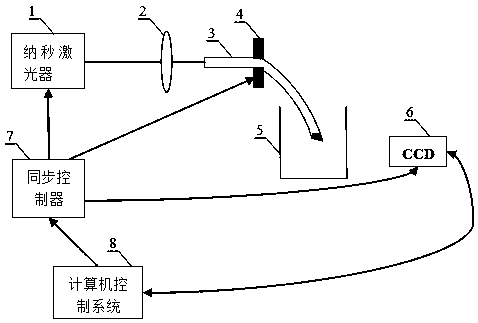
[0006] Aiming at the technical problem that the simple combination of the photoacoustic effect and the sound wave-driven fluid effect cannot produce macroscopic liquid flow, the present invention proposes a laser-driven macroscopic liquid flow device and method based on an optical fiber. The acoustic effect and the acoustic wave-driven fluid effect are perfectly coupled together. The injection technology is used to inject gold nanoparticles into one end face of the fiber, and at the same time couple the nanosecond laser pulse into the fiber through the other end face of the fiber. The gold nanoparticles injected into the fiber are under the action of the laser. Ultrasonic waves are generated due to the photoacoustic effect, and at the same time, the liquid near the optical fiber is caused to flow due to the sound wave-driven fluid effect, thereby realizing the high-speed flow of macroscopic liquid

Method used


Image

  • Laser-driven macroscopic liquid flow device and method based on optical fiber
  • Laser-driven macroscopic liquid flow device and method based on optical fiber
  • Laser-driven macroscopic liquid flow device and method based on optical fiber

Examples


specific example

[0045] Further, the optical fiber 3 is a multimode optical fiber with a core diameter of 200 μm and a length of 30 cm. One end of the optical fiber 3 is injected with gold nanoparticles using injection technology, and the injection amount is usually 4×10 16 Au / cm 2 , the injection energy is 60keV.

[0046] The nanosecond laser 1 emits laser pulses with a wavelength of 527nm, a pulse width of 150ns, and an average power of 120mW. Lens 2 is a short focus lens with a focus of 50mm. CCD 6 is a photodetector with a pixel size of 1280×1024. CCD 6 is PixelinkPL-B742U type CCD. Synchronous controller 7 adopts 12-bit A / D and D / A conversion inside, and the resolution can reach 0.1%. The computer control system 8 is a general PC.

[0047] according to figure 1 Connect the components in the structure shown, and open the control software of the laser-driven liquid flow device in the computer control system 8. This control software is based on the WINDOWS operating system and uses the...


PUM

PropertyMeasurementUnit
Wavelengthaaaaaaaaaa
Pulse widthaaaaaaaaaa

Abstract

The invention provides a laser-driven macroscopic liquid flow device and method based on optical fiber which is used for solving the problem that macroscopic liquid flow cannot be produced through simple combination of a photoacoustic effect and a sound wave driving fluid effect. According to the laser-driven macroscopic liquid flow device and method based on the optical fiber, nanometer gold particles are injected into one end face of the optical fiber by adopting an injection technology, and fixed and immersed in a driven solution, meanwhile, a nanosecond laser pulse is coupled into the optical fiber from the other end face of the optical fiber, and the laser pulse interacts with the nanometer gold particles injected into the optical fiber; the nanometer gold particles produce ultrasoundunder the effect of laser due to the photoacoustic effect, and meanwhile, a liquid is driven to flow due to the sound wave driving fluid effect; a fixed liquid-liquid interface and a liquid flow channel are needed, special requirements for the flowing liquid and the environment do not exist, the laser-driven macroscopic liquid flow device and method based on optical fiber is suitable for any liquids, tenability of the flow speed and direction of the driven liquid can be achieved, flowing of the driven liquid is monitored on line in real time by adopting a CCD, the control accuracy is improvedgreatly, and operation is convenient and easy.

Description

technical field [0001] The invention relates to the technical field of interdisciplinary subjects such as optoelectronics, acoustics, nano preparation, fluid dynamics, and solid mechanics, and can be applied in the fields of laser drive, microfluidics, laser surgical cleaning, transportation, or liquid mixing, etc. An optical fiber-based laser-driven macroscopic liquid flow device and method. Background technique [0002] The birth of the first laser in 1960 marked the entry of optoelectronic technology into a new field. However, with the vigorous development of optical technology, traditional solid-state optical devices are difficult to meet the increasing miniaturization, integration, and adjustable modern optical technology. The development of technology has brought greater challenges to laser manipulation technology and driving technology, especially laser-driven liquid flow technology. Laser not only represents high intensity and directionality, but also has mechanical...

Claims


Application Information

Patent Timeline
IPC IPC(8): F04B19/00
CPCF04B19/00
Inventor 张秋慧栗科峰付国定徐勉之
Owner 深圳市比洋光通信科技股份有限公司
Learn More