Closed heat-dissipating charging pile

A charging pile and heat-dissipating technology, which is applied in the field of closed heat-dissipating charging piles, can solve the problems of clogging dust-proof cotton, excessive heat generation of electrical components, and rising temperature of charging piles, so as to prevent rain and dust from entering, improve cooling effect, The effect of improving the protection level

Pending Publication Date: 2018-07-06
NANJING SKYSOURCE POWER TECH CO LTD
View PDF0 Cites 11 Cited by
  • Summary
  • Abstract
  • Description
  • Claims
  • Application Information

AI Technical Summary

Problems solved by technology

The existing charging piles for new energy vehicles are generally placed outdoors, and the working environment is relatively harsh. The power itself is very high, and the electrical components inside the charging pile generate more heat, which causes the internal temperature of the charging pile to rise, which has a negative effect on the charging pile. The normal operation of electrical components is affected
This requires that the charging pile can dissipate the heat emitted by electrical components to the outside air. The current heat dissipation method is forced air convection heat dissipation, and the heat dissipation effect is not ideal. There are hidden dangers of low reliability and safety when used in electric vehicle charging piles.
The traditional heat dissipation is forced air convection by the fan. The air outlet and air inlet of the fan are easily entered by rainwater and dust. Although there are measures such as dust-proof cotton, in actual use, the sand and dust will block the dust-proof cotton, resulting in air not being able to circulate. , causing a safety hazard

Method used


Image

  • Closed heat-dissipating charging pile
  • Closed heat-dissipating charging pile

Examples


Embodiment Construction

[0010] The present invention will be further described below in conjunction with the accompanying drawings.

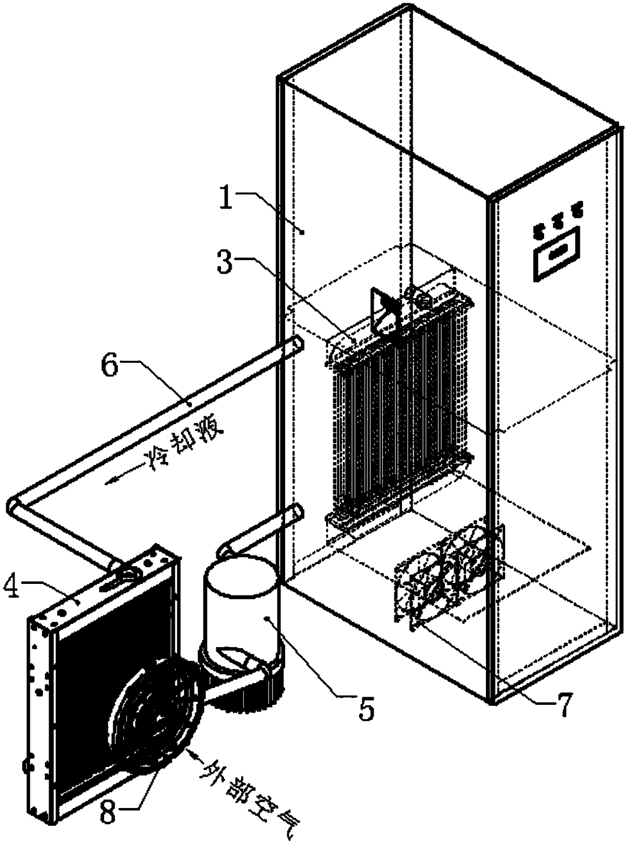
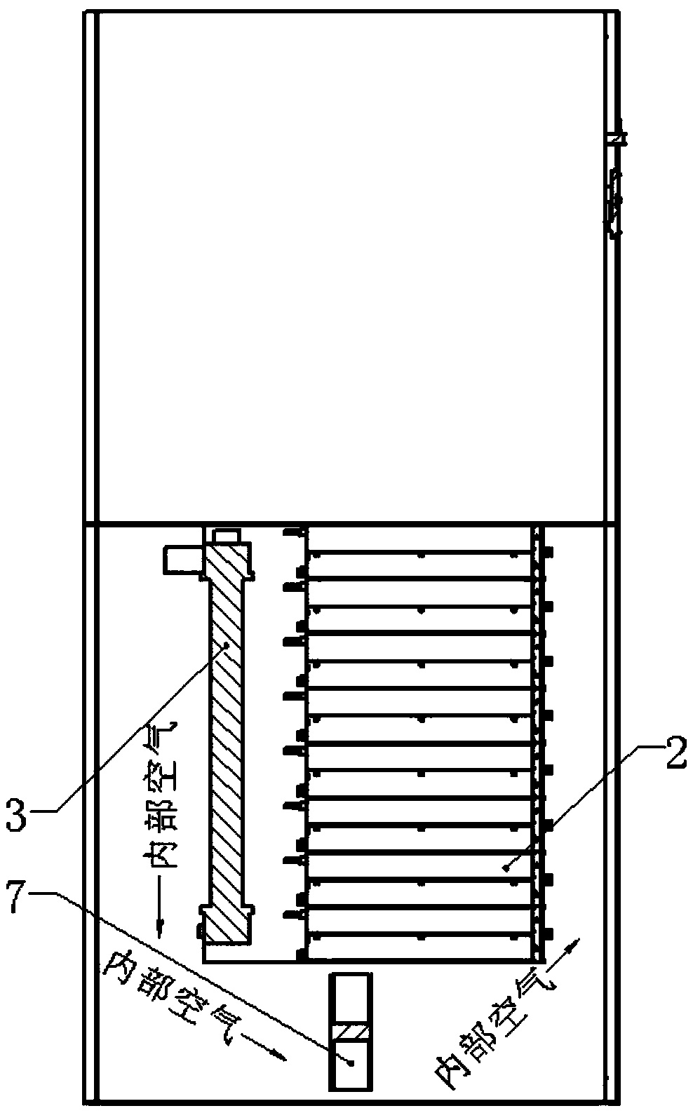
[0011] Such as figure 1 and figure 2 , a closed heat dissipation charging pile of the present invention, comprising a power cabinet 1, a charging module 2, an internal radiator 3, an external radiator 4, a water pump 5, a water pipe 6, an internal fan 7 and an external fan 8, a charging module 2, an internal heat dissipation The radiator 3 and the internal fan 7 are arranged in the inner cavity of the power cabinet 1, the external radiator 4, the water pump 5 and the external fan 8 are placed outside the power cabinet 1, and the external fan 8 is placed on the side of the external radiator 4. The internal radiator 3 and the external radiator 4 are connected through a water pipe 6, and the external radiator 4 and the water pump 5 are connected through a water pipe 6. The internal radiator 3, the external radiator 4, the water pump 5 and the water pipe 6 is filled wit...


PUM


Abstract

The invention discloses a closed heat-dissipating charging pile. A charging module, an internal radiator and internal fans are arranged in an inner chamber of a power cabinet, an external radiator, awater pump and an external fan are arranged outside the power cabinet, the external fan is placed at one side of the external radiator, the internal radiator and the external radiator are communicatedthrough a water pipe, the external radiator and the water pump are communicated through the water pipe, and the internal radiator, the external radiator, the water pump and the water pipe are filledwith cooling liquid. The charging pile uses the cooling liquid for cooling, the cooling effect is improved, and the reliability of charging pile work is improved. By adopting a heat exchange manner for cooling, the charging pile can be made into a closed structure, so that the IP protection level of the charging pile is improved, rainwater and dust are prevented from entering the charging pile, and the reliability of operation of electronic components is improved; the charging pile can be made into the closed structure, so that the security is improved.

Description

Technical field: [0001] The invention relates to a closed heat dissipation charging pile. Background technique: [0002] Under the background of energy constraints and environmental pollution, the Chinese government regards the development of new energy vehicles as a major measure to solve energy and environmental problems and achieve sustainable development. Automobile manufacturers also regard new energy vehicles as an important strategy to seize the commanding heights of the future automobile industry. Strategic Direction. With the joint efforts of the government and enterprises, my country's new energy vehicle industry has shown a good momentum of development in recent years. The continuous development of new energy vehicles must be equipped with charging piles suitable for its development. The existing charging piles for new energy vehicles are generally placed outdoors, and the working environment is relatively harsh. They have high power, and the electrical component...

Claims


Application Information

Patent Timeline
Patent Type & Authority Applications(China)
IPC IPC(8): B60L11/18H05K7/20
CPCB60L53/31H05K7/20909H05K7/20927Y02T10/70Y02T10/7072Y02T90/12
Inventor 许善玉葛太全王峰陶也
Owner NANJING SKYSOURCE POWER TECH CO LTD
Why Eureka
Try Eureka