
Welding equipment convenient to move

It is a welding equipment and a technology that is convenient to move. It is used in the transportation of filamentous materials, thin material processing, transportation and packaging. It can solve the problems of reducing corporate profits, consuming manpower and time, and complicated procedures, improving work efficiency and reducing The effect of manual operation

Inactive Publication Date: 2018-07-03
贾军霞
View PDF0 Cites 0 Cited by
  • Summary
  • Abstract
  • Description
  • Claims
  • Application Information

AI Technical Summary

Problems solved by technology

Then it is necessary to remove the solder wire that has been rolled into a tube from the solder wire tube. The process of unloading the tube-shaped solder wire is more complicated, and then replace the new solder wire tube to re-coil, and then start the next round of winding. This method is inefficient and requires more manpower and time, which affects the overall soldering process and reduces the profit of the enterprise.

Method used


Image

  • Welding equipment convenient to move
  • Welding equipment convenient to move
  • Welding equipment convenient to move

Examples


Embodiment Construction

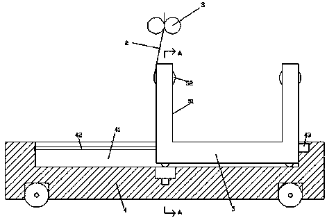
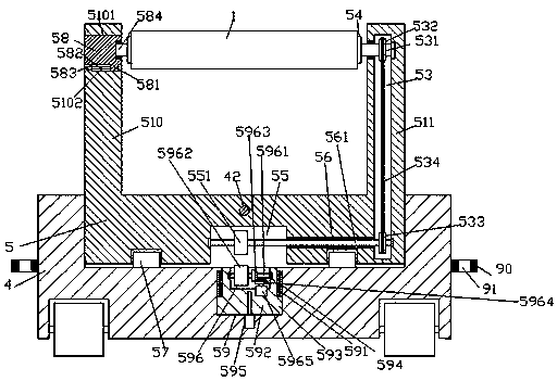
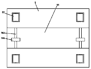
[0025] Such as Figure 1-Figure 6 As shown, a convenient mobile welding device of the present invention includes a frame body 4 and a gripper 3 arranged above the top of the frame body 4 and oppositely arranged left and right. The bottom of the frame body 4 is provided with a rotating wheel 401, so that The rotating wheel 401 is used to conveniently move the position of the frame body 4, the frame body 4 is provided with a first guide groove 41, and the first guide groove 41 is movable and connected to the bottom frame 5, and the first guide groove 41 is movable and connected to the bottom frame 5. The center position of the bottom of the guide groove 41 is provided with a first sliding groove 59, and the front and rear sides of the first sliding groove 59 are equally provided with a second guiding groove 591, and the first sliding groove 59 is provided with a first Sliding block 592, the front and rear sides of the bottom of the first sliding block 592 are respectively provid...


PUM


Abstract

The invention discloses welding equipment convenient to move. The welding equipment convenient to move comprises a frame body and clamps, wherein the clamps are arranged above the top of the frame body and are leftwards-and-rightwards oppositely arranged. The bottom of the frame body is provided with rotating wheels. The frame body is internally provided with a first guide groove. The first guidegroove is internally and movably connected with a bottom frame in a cooperative manner. A first sliding and conveying groove is formed in the center position of the bottom of the first guide groove. The front side and the back side of the first sliding and conveying groove are symmetrically provided with second guide grooves. The first sliding and conveying groove is internally provided with a first sliding and conveying block. The front side and the rear side of the bottom of the first sliding and conveying block are provided with first guide blocks which penetrate the second guide groove inthe front side and the second guide groove in the rear side. A perforated groove which extends leftwards and rightwards is formed in the center position of the bottom end face of the bottom frame. Thewelding equipment convenient to move is simple in structure, the leftward and rightward moving of the bottom frame can be automatically controlled, the work that a left support device and a right support device are switched to take up a tin wire and tin rolling cylinders are dismounted and changed is achieved, the mounting and demounting convenience is improved, and the tin wire rolling process is not affected.

Description

technical field [0001] The invention relates to the field of welding technology, in particular to a convenient mobile welding equipment. Background technique [0002] After the solder wire is produced and processed into a linear shape, the solder wire coil needs to be collected to facilitate storage and transportation. The existing solder wire coil machine includes two relatively movable supports and a solder coil set on the two supports. The wire spool, the solder wire drum sleeved on the solder wire drum, and the electric rotating machine that drives the solder wire shaft to rotate; when winding the solder wire, first fix one end of the solder wire on the solder wire drum, and turn on the electric motor. Carry out the solder wire winding action. Then it is necessary to remove the solder wire that has been rolled into a tube from the solder wire tube. The process of unloading the tube-shaped solder wire is more complicated, and then replace the new solder wire tube to re-c...

Claims


Application Information

Patent Timeline
Patent Type & Authority Applications(China)
IPC IPC(8): B65H54/40B65H54/553B65H54/74
CPCB65H54/40B65H54/553B65H54/74B65H2701/36
Inventor 贾军霞何杨波
Owner 贾军霞
Learn More