
Switch component for direct-current breaker and direct-current breaker

A technology for DC circuit breakers and switch components is applied in the field of switch components for DC circuit breakers and DC circuit breakers.

Active Publication Date: 2018-06-29
XJ ELECTRIC +1
View PDF5 Cites 7 Cited by
  • Summary
  • Abstract
  • Description
  • Claims
  • Application Information

AI Technical Summary

Problems solved by technology

[0005] The purpose of the present invention is to provide a switch assembly for a DC circuit breaker and a DC circuit breaker, which are used to solve the problem that the existing equipment structure layout is no longer suitable for a specific DC circuit breaker topology

Method used


Image

  • Switch component for direct-current breaker and direct-current breaker
  • Switch component for direct-current breaker and direct-current breaker
  • Switch component for direct-current breaker and direct-current breaker

Examples


Embodiment Construction

[0034] In order to make the object, technical solution and advantages of the present invention clearer, the present invention will be further described in detail below in conjunction with the accompanying drawings and specific embodiments.

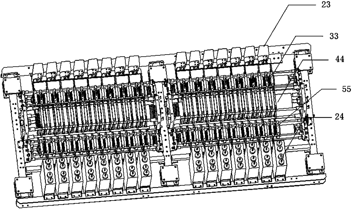
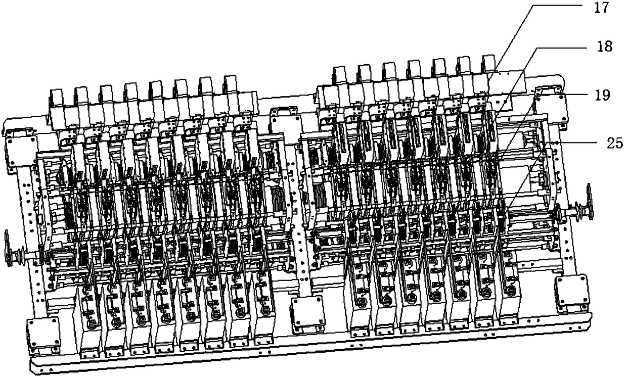
[0035] The electrical schematic diagram of the switch assembly for the DC circuit breaker provided by the present invention is as follows: figure 1 As shown, the switching assembly includes more than two switching power modules connected in series, wherein any switching power module includes a parallel first bridge arm, a second bridge arm, a first full control device valve group, a second full control The device valve group and absorption circuit, the first bridge arm and the second bridge arm are connected in parallel in the same direction to form an H-bridge module. by figure 1Take the switching power module on the left as an example, the first bridge arm is composed of the uncontrolled device valve group composed of the upper bridge a...


PUM


Abstract

The invention relates to a switch component for a direct-current breaker and the direct-current breaker. The switch component comprises switch power modules, each of the switch power modules comprisesa first bridge arm and a second bridge arm, which are connected in series, as well as a capacitance valve group and at least two fully controlled device valve groups; the first bridge arm and the second bridge arm are both formed by connecting two uncontrolled device valve groups in series in the same direction; the switch component further comprises a front-row uncontrolled device valve segment,a fully controlled device valve segment and a rear-row uncontrolled device valve segment which are successively arranged at intervals along the front-and-back direction, in each switch power module,the uncontrolled device valve groups in the first bridge arm and the second bridge arm are connected in the front-row uncontrolled device valve segment in a pressed mode, the uncontrolled device valvegroup in the lower bridge arm is connected in the rear-row uncontrolled device valve segment in a pressed mode, and the fully controlled device valve groups are connected in the fully controlled device valve segment in a pressed mode. By symmetrically arranging the front-row uncontrolled device valve segment and the rear-row uncontrolled device valve segment on two sides of the fully controlled device valve segment, the switch component not only has a compact structure and is high in modularization degree but also is convenient for assembly and wiring.

Description

technical field [0001] The invention relates to a switch assembly for a DC circuit breaker and a DC circuit breaker, belonging to the technical field of high-voltage DC circuit breakers. Background technique [0002] At present, there are three main types of technical solutions for DC circuit breakers, namely traditional mechanical DC circuit breakers based on conventional switches, solid-state DC circuit breakers based on pure power electronic devices, and hybrid DC circuit breakers based on the combination of the two. With the continuous improvement of controllable power device manufacturing technology, hybrid DC circuit breakers have developed rapidly. [0003] Among them, the topology structure widely used in the hybrid DC circuit breaker is: the parallel connection of the flow main branch and the transfer branch. The main flow branch is composed of a group of auxiliary switch power modules and mechanical switches in series, and the transfer branch is composed of a larg...

Claims


Application Information

Patent Timeline
IPC IPC(8): H02H3/087H02H3/02H05K7/20
CPCH02H3/02H02H3/087H05K7/2089
Inventor 姚为正胡四全宋全刚肖晋李申焦洋洋孙晶晶朱新华
Owner XJ ELECTRIC
Learn More