
Electric crank for handcart-type switch cabinet

A handcart-type switch, electric technology, applied in the direction of pull-out switch cabinets, electric components, switch devices, etc., can solve the problem of not being able to get better applications, and achieve the effect of convenient operation

Pending Publication Date: 2018-06-29
魏怡琪
View PDF8 Cites 5 Cited by
  • Summary
  • Abstract
  • Description
  • Claims
  • Application Information

AI Technical Summary

Problems solved by technology

The device adopts an electric device to improve the predicament in the operation process. However, since the moving and static contacts of the handcart switch require a large force during the opening and closing process, the structure of the device is used in the power transformation and distribution environment where a large number of female workers work. Due to the ease of handling and force, it cannot be better applied

Method used

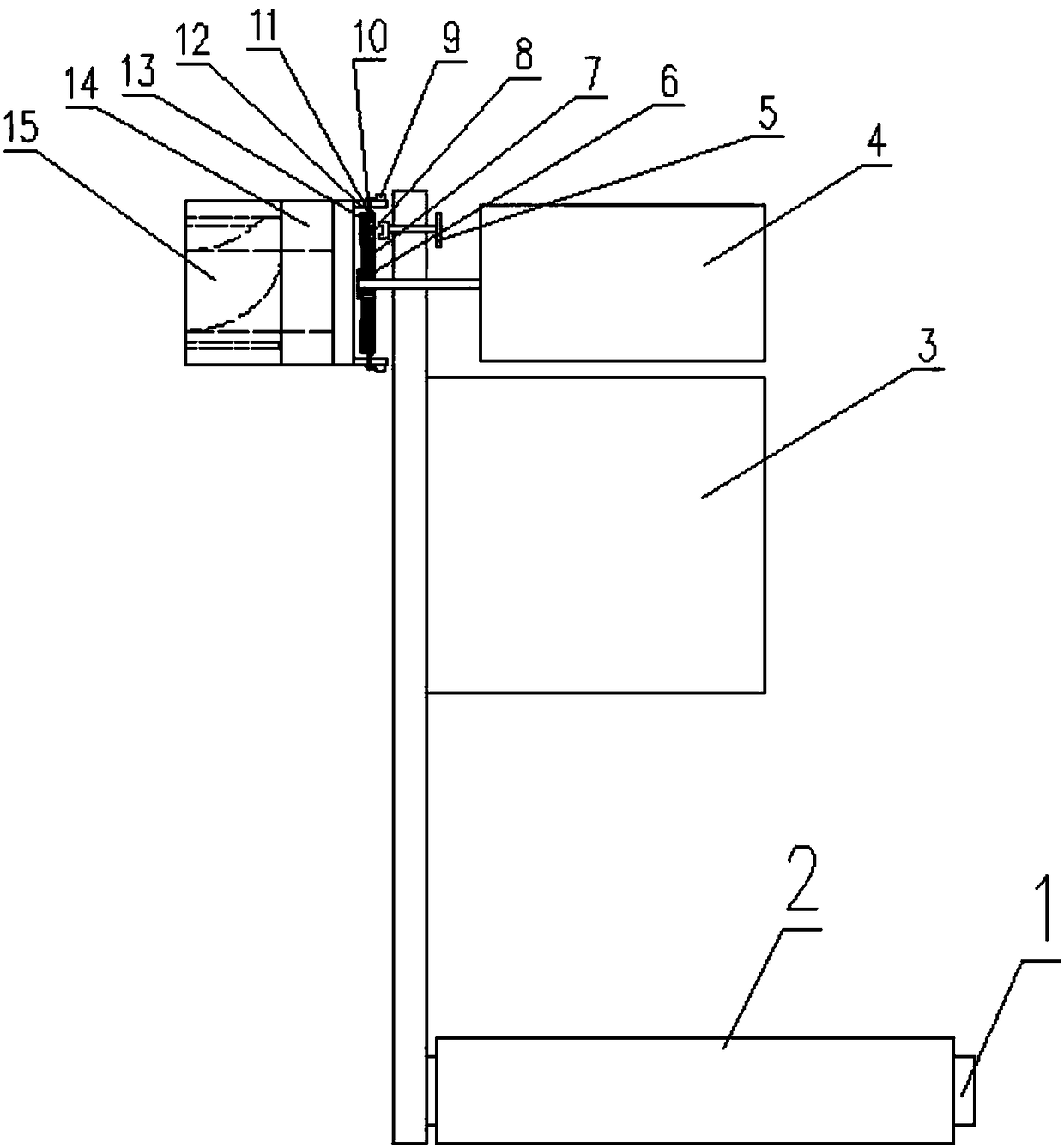

Image

  • Electric crank for handcart-type switch cabinet
  • Electric crank for handcart-type switch cabinet
  • Electric crank for handcart-type switch cabinet

Examples


Embodiment Construction

[0023] The present invention will be further described below in conjunction with the accompanying drawings and embodiments.

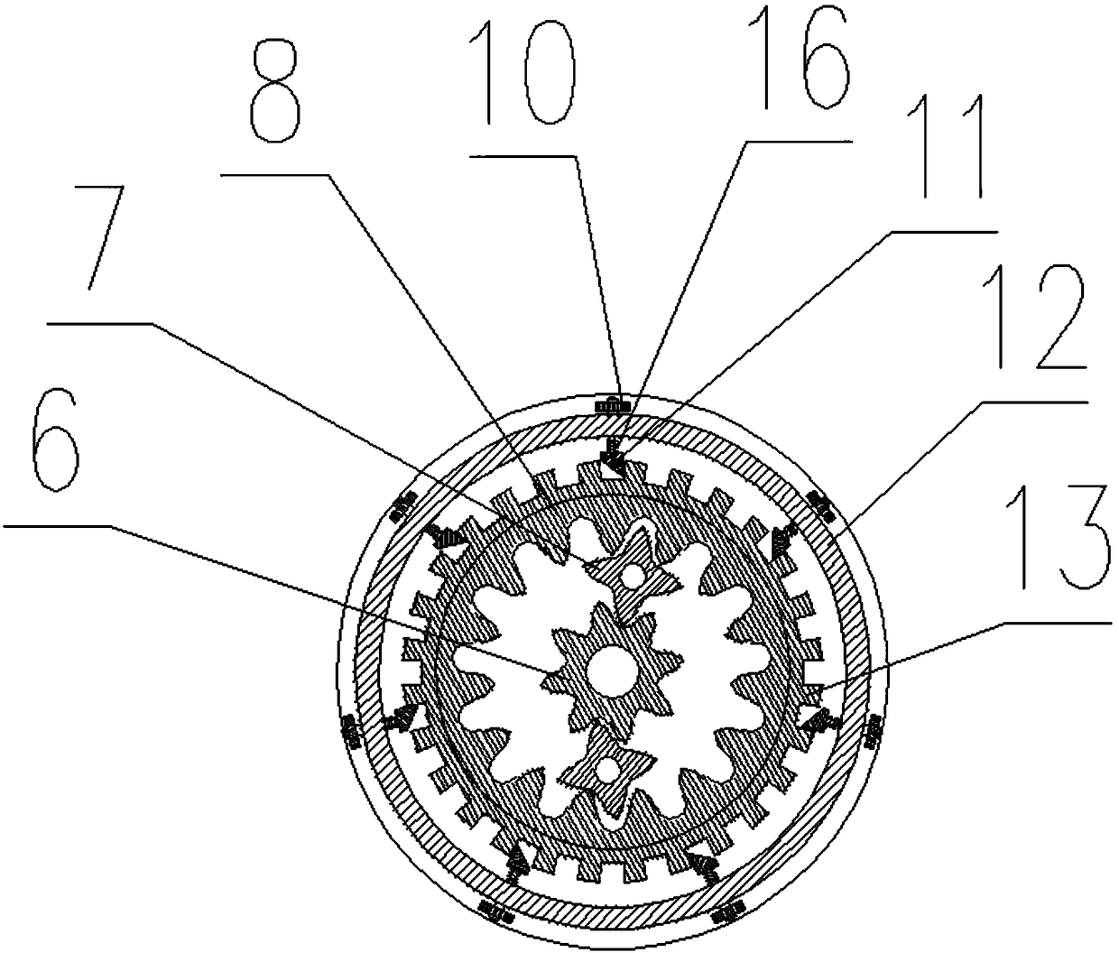
[0024] Such as figure 1 As shown, a handcart type switch cabinet electric crank, including a rocker arm, the two ends of the rocker arm are respectively provided with a handle 1 and a crank head, which is characterized in that: the rocker head includes an electric structure placed on one side of the rocker arm, and The two-way ratchet mechanism, the planetary gear mechanism and the sleeve structure on the other side of the rocker arm, the sleeve structure is at the front end, and the planetary gear structure is arranged inside the two-way ratchet structure; the handle 1 is provided with a rubber grip 2, so The rubber handle 2 is provided with dot-shaped protrusions;

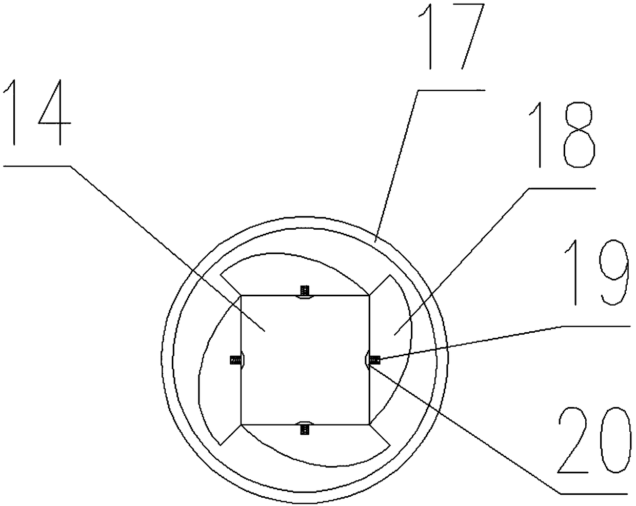
[0025] Such as figure 2 As shown, the sleeve structure includes a sleeve portion 14 and a guide portion 15. The sleeve portion 14 is a common structure with a square opening in the mout...


PUM


Abstract

The invention discloses an electric crank for a handcart-type switch cabinet and relates to the technical field of power supply and distribution equipment. The electric crank comprises a handle, a rocker arm and a crank head, wherein the crank head comprises a sleeve structure, a two-way ratchet mechanism, a planetary gear mechanism and an electric structure. With adoption of the handle, the defect that holding and stress are inconvenient in the prior art is overcome, and the electric crank is convenient to mount and has manual and electric dual-purpose effect.

Description

technical field [0001] The invention relates to the technical field of power supply and distribution equipment, in particular to an electric crank for a handcart type switch cabinet. Background technique [0002] The handcart switchgear has three positions of operation, test and maintenance. The switch between the operating position and the test position requires the operator to drive the handcart rocker arm to rotate by shaking the handle on the handcart handle, and then make the handcart crank The rear end of the arm is connected by a spring-loaded detent and rotates on a central axis located in the cabinet. The operator turns the handle to drive the screw to rotate, so that the switchgear trolley moves back and forth. When the trolley switchgear is in the operating position, the moving contacts on it are connected to the static contacts on the bus; when the trolley switchgear is in the test position, the moving and static contacts are separated. However, during the swit...

Claims


Application Information

Patent Timeline
Patent Type & Authority Applications(China)
IPC IPC(8): H02B11/167H02K7/10
CPCH02B11/167H02K7/10
Inventor 魏怡琪
Owner 魏怡琪
Learn More