
Automatic tracking method and system adopting biaxial pan tilt

An automatic tracking, PTZ technology, applied in the direction of using feedback control, etc., can solve the problems of inaccurate direction positioning, low real-time requirements, difficult UAV position, etc., to achieve long data transmission distance, strong environmental adaptability, Strong anti-interference ability

Inactive Publication Date: 2018-06-29
深圳市科卫泰实业发展有限公司
View PDF5 Cites 9 Cited by
  • Summary
  • Abstract
  • Description
  • Claims
  • Application Information

AI Technical Summary

Problems solved by technology

However, the current research on directional antenna alignment mostly focuses on the situation where both sides of the communication are relatively stationary, and the real-time requirements are low. The alignment method of the antenna attitude angle is relatively simple, and it is difficult to determine the position of the UAV in real time and with high precision.
[0003] At present, the UAV ground station uses a directional antenna to locate the UAV, which requires manual operation. The directional antenna needs to be manually aligned with the UAV. The direction positioning is not accurate, and there will be tracking after the UAV flies out of the line of sight. Difficult, especially in bad weather such as rain and fog, it is difficult to operate, and the error is large; in addition, the directional antenna pan / tilt of the ground station will rotate continuously in the horizontal direction, which is easy to wind

Method used


Image

  • Automatic tracking method and system adopting biaxial pan tilt
  • Automatic tracking method and system adopting biaxial pan tilt
  • Automatic tracking method and system adopting biaxial pan tilt

Examples


Embodiment Construction

[0026] In order to make the object, technical solution and advantages of the present invention clearer, the present invention will be further described in detail below in conjunction with the accompanying drawings and embodiments. It should be understood that the specific embodiments described here are only used to explain the present invention, not to limit the present invention.

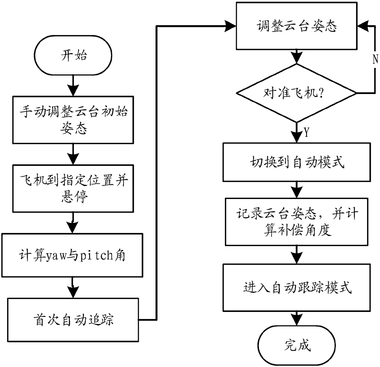
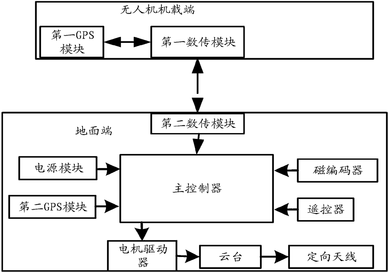
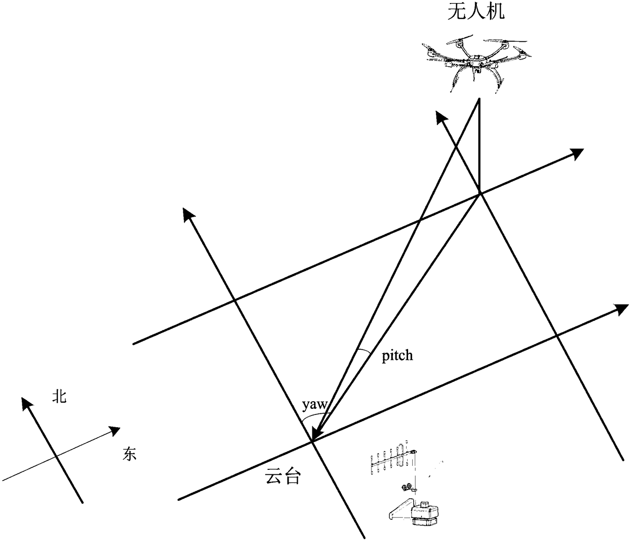
[0027] In view of the current UAV ground station using a directional antenna to locate the UAV, there are problems such as inaccurate direction positioning, difficult tracking, difficult operation and easy winding. The purpose of the present invention is to provide a dual-axis pan-tilt automatic tracking method, this method controls the UAV to take off and hover at any initial position of the gimbal, and then receives the GPS signal of the UAV and the GPS signal of the gimbal itself, and calculates the current distance between the two in latitude, longitude and altitude. Calculate the required rota...


PUM


Abstract

The invention provides an automatic tracking method adopting a biaxial pan tilt. The method comprises the following steps: calculating longitude and latitude distances between an airborne end of an unmanned aerial vehicle and a ground end pan tilt and a height distance between the airborne end of the unmanned aerial vehicle and the ground end pan tilt under a current position; calculating a yaw angle theta 1 and a pitch angle theta 2, relative to the ground end pan tilt, of the unmanned aerial vehicle according to the longitude and latitude distances and the height distance; controlling corresponding rotation of the ground end pan tilt according to the yaw angle theta 1 and the pitch angle 2, and aligning a ground end directional antenna to the airborne end of the unmanned aerial vehicle.In addition, the invention also provides a biaxial pan tilt automatic tracking system. Compared with the prior art, the method and the system disclosed by the invention have the advantages that small-error alignment can be realized when a distance of the unmanned aerial vehicle is further, and continuous rotation can be realized in the horizontal direction without winding wires. The method and thesystem disclosed by the invention have the advantages of strong adaptive capacity to environment, long data transmission distance, strong anti-interference ability and the like, and can meet market demands more preferably.

Description

technical field [0001] The invention relates to a tracking technology for a pan-tilt of an unmanned aerial vehicle, in particular to a method and system for automatic tracking of a two-axis pan-tilt. Background technique [0002] In order to improve the efficiency of information transmission and the security of ground communication stations, the research of using unmanned aerial vehicle as a communication platform and using directional antennas in ground stations has attracted extensive attention. However, the current research on directional antenna alignment mostly focuses on the situation where both communication parties are relatively stationary, and the real-time requirements are low. The alignment method of the antenna attitude angle is relatively simple, and it is difficult to determine the position of the UAV in real time and with high precision. [0003] At present, the UAV ground station uses a directional antenna to locate the UAV, which requires manual operation. ...

Claims


Application Information

Patent Timeline
IPC IPC(8): G05D3/12
CPCG05D3/12
Inventor 郭洪振丁红亮李明富李建生靖恩
Owner 深圳市科卫泰实业发展有限公司
Learn More