
Pneumatic-based electrospinning device

A technology of electrospinning and air supply device, applied in textiles and papermaking, filament/thread forming, fiber processing, etc., can solve the problems of unstable jet flow, affecting electrospinning, waste of resources, etc. Reduce charge interference, reduce the effect of charge interference

Inactive Publication Date: 2018-06-29
NANJING UNIV OF SCI & TECH
View PDF4 Cites 3 Cited by
  • Summary
  • Abstract
  • Description
  • Claims
  • Application Information

AI Technical Summary

Problems solved by technology

[0004] The traditional electrospinning device usually spins up to 1.5g per hour, or can spray up to 6ml per hour, and the efficiency of electrospinning is very low
In recent years, the method to improve the efficiency of electrospinning is mainly to use a multi-needle electrospinning device for mass production, but due to the electrostatic repulsion, the spraying state of each spraying needle is inconsistent, and it is difficult to ensure continuous spinning of each spraying needle. At the same time, the electrostatic repulsion also makes the jet unstable, which makes the shape and size of the nanofibers vary greatly, which affects the quality of the nanofiber membrane.
Some also introduce high-pressure gas to improve efficiency, but it is greatly affected by environmental parameters, especially the influence of humidity. When the humidity is high, when the gas is supplied by the air supply pump, the gas contains more water, which affects the electrospinning process.
At present, the nozzles used in large-scale electrospinning devices are difficult to disassemble, and are easy to block and difficult to clean, resulting in a great waste of resources and seriously hindering the development of electrospinning.

Method used


Image

  • Pneumatic-based electrospinning device
  • Pneumatic-based electrospinning device
  • Pneumatic-based electrospinning device

Examples


Embodiment Construction

[0028] The present invention will be further described below in conjunction with drawings and embodiments.

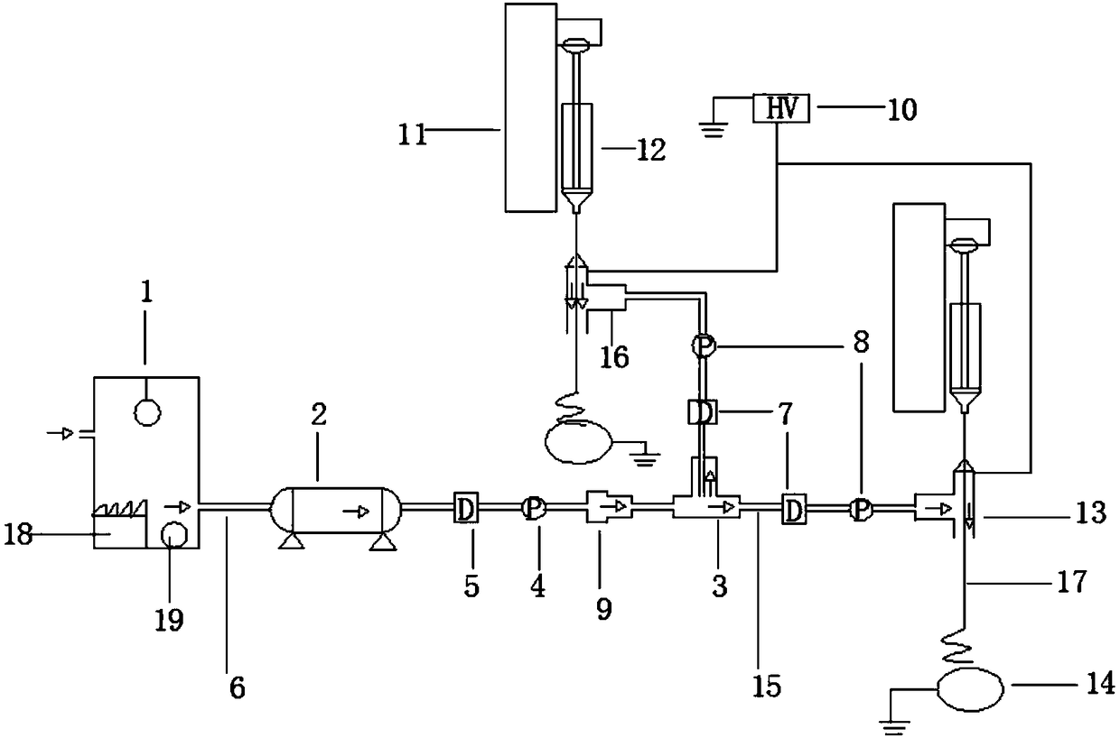
[0029] see Figure 1~3 , the embodiment of the present invention is equipped with a gas supply device, a gas distribution device and a spray device;

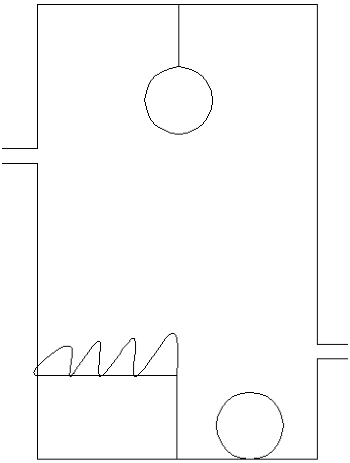
[0030] The gas supply device includes: a gas drying device 1 connected in sequence, an air compressor 2, and a gas conduit adapter device 9; the gas supply devices are connected through a gas conduit 6 with an inner diameter of 6 to 8 mm; A pressure regulating valve 5 and a gas pressure gauge 4 are arranged between the gas conduit adapters 9 . In the gas drying device 1 , a desiccant 19 and a temperature raising device 18 are provided inside.

[0031] The gas distribution device 3 connected to the gas conduit adapter device 9 is connected to the injection device; the gas supply device and the injection device are connected through a gas conduit 15 with an inner diameter of 3-5 mm. An auxiliary pressure regulating valve...


PUM


Abstract

The invention discloses a pneumatic-based electrospinning device. A gas supply device, a gas flow distribution device and an injection device are arranged, wherein the gas supply device introduces high-pressure gas flow to transfer the surface charge of jet flows, reduce the surface charge density, reduce the charge interference between the jet flows and refine nanofibers to improve the quality ofthe nanofibers; through a gas guiding device, a gap is reserved between jet needles to further reduce the charge interference between the jet flows; a drying device reduces the influence of humidityon operating conditions, so that the influence of environmental parameters on electrospinning is reduced; the used jet needles are easy to disassemble, easy to clean and easy to replace. The electrospinning device can improve the quality of electrospinning and significantly improve the yield of electrospinning, the problems of conventional electrospinning are solved, and a device for electrospinning by using sheath gas in recent years is improved to provide the possibility of industrialization of electrospinning.

Description

technical field [0001] The invention relates to an electrospinning device, in particular to a pneumatic-based electrospinning device which improves the efficiency of electrospinning by utilizing sheath gas shunt flow. Background technique [0002] Electrospinning technology refers to a method in which a polymer solution or melt is sprayed and stretched under the action of a high-voltage electrostatic field, and the solvent is volatilized and solidified to obtain a fibrous material. Electrospinning technology has the advantages of simple process, wide range of spinnable polymers and low cost. Compared with other conventional spinning processes, the most important feature of electrospinning is that nanofibers with large specific surface area, high porosity, small pore size and large aspect ratio can be obtained. The process parameters of electrospinning mainly include the properties of the polymer solution, process parameters and environmental parameters (including temperatur...

Claims


Application Information

Patent Timeline
IPC IPC(8): D01D5/00
CPCD01D5/0061
Inventor 冯章启李通史传梅袁旭严珂夏一鹭
Owner NANJING UNIV OF SCI & TECH
Learn More