
High-voltage system circuit of new energy vehicle

A new energy vehicle and high-voltage system technology, applied in the field of new energy vehicles, to achieve the effect of prolonging the service life and saving charging energy consumption

Inactive Publication Date: 2018-06-29
武汉斯马特益电子技术有限公司
View PDF0 Cites 5 Cited by
  • Summary
  • Abstract
  • Description
  • Claims
  • Application Information

AI Technical Summary

Problems solved by technology

[0005] The purpose of the present invention is to solve the problems existing in the existing high-voltage circuit structure of new energy vehicles, and to provide a high-voltage system circuit for new energy vehicles, which does not require high-voltage circuits such as pre-charging relays, main positive relays, and inverters to realize external charging of vehicles. Parts work, and can ensure that when the whole vehicle is powered off, the high-voltage system circuit can complete the charge discharge of the capacitive device within the specified safety time
According to the topology of the circuit structure of the high-voltage system, the power-on and power-off control is carried out according to the following process:

Method used


Image

  • High-voltage system circuit of new energy vehicle
  • High-voltage system circuit of new energy vehicle
  • High-voltage system circuit of new energy vehicle

Examples


Embodiment Construction

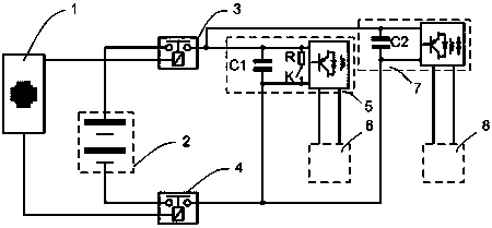
[0023] combined with figure 1 As shown, the high-voltage system circuit of the new energy vehicle of the present invention includes a control system 1 (the specific control function can be composed of a single or two or more controller combination), power battery 2, power relay 3, main negative relay 4, DC converter 5, low-voltage circuit system 6, vehicle charger 7 and mains power system 8. The DC converter 5 has a bidirectional conversion function or has a built-in independent capacitor self-charging circuit, and a controllable charge rapid discharge circuit is provided on the high-voltage DC side of the DC converter 5 (or the on-board charger 7), and the DC converter 5 and the on-board charging The circuit on the high-voltage DC side of the machine 7 is directly connected and shares one power supply relay 3 .

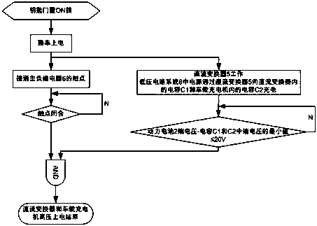
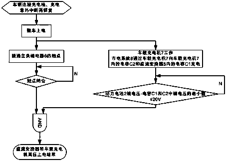
[0024] combined with figure 2 , attached image 3 And attached Figure 4 , the new energy vehicle high voltage system circuit of the present invention comprises...


PUM


Abstract

The invention belongs to the field of new energy vehicles, and particularly relates to a high-voltage system circuit of a new energy vehicle and power up and down work control procedures of capacitivedevices in the high-voltage system circuit. The high-voltage system circuit of the new energy vehicle comprises a control system (with particular control functions capable of being implemented by a single controller such as vehicle control units, battery management controllers, power motor controllers, direct-current converters and vehicular chargers or a combination of more than two of the controllers), a power battery, a power supply relay, a main negative relay, a direct-current converter, a low-voltage circuit system, a vehicular charger and a mains supply system. The direct-current converter has bidirectional conversion functions or is provided with built-in capacitive self-charge circuits, electric charge quick release circuits are arranged on high-voltage direct-current sides of the direct-current converter (or the vehicular charger), circuits on the high-voltage direct-current sides of the direct-current converter and the vehicular charger are directly connected with one another, and the same power supply relay is shared by the direct-current converter and the vehicular changer.

Description

technical field [0001] The invention belongs to the field of new energy vehicles, and in particular relates to a high-voltage system circuit of a new energy vehicle, and a work control process such as charging and discharging of a capacitive device in the high-voltage system circuit when it is powered on. Background technique [0002] The development of the new energy vehicle industry is an important measure to implement the national energy transformation and upgrading strategy. With the introduction of the dual credit management system for the automotive industry, the new energy vehicle market will usher in a blowout-style rapid development. [0003] The energy consumption, safety and reliability of the high voltage system of new energy vehicles are the key factors affecting the quality and market of new energy vehicles. [0004] In order to avoid the capacitive devices existing in the high-voltage circuit from being damaged due to excessive transient load due to excessive ...

Claims


Application Information

Patent Timeline
IPC IPC(8): B60L11/18
CPCB60L53/00Y02T10/70Y02T10/7072Y02T10/72Y02T90/14
Inventor 董秀辉刘晓伟刘慧琳罗玮周欢刘佩
Owner 武汉斯马特益电子技术有限公司
Learn More