Limiting structure for limiting displacement of mould floating template

A floating template and limit structure technology, applied in manufacturing tools, forming tools, metal processing equipment, etc., can solve the problems of reducing the rigidity and deflection of the L-shaped limit block, increasing the thread diameter, reducing the safety factor, etc. Simple structure, improved limit accuracy and low processing cost

Active Publication Date: 2018-06-29
天津市津兆机电开发有限公司
View PDF7 Cites 2 Cited by
  • Summary
  • Abstract
  • Description
  • Claims
  • Application Information

AI Technical Summary

Problems solved by technology

When the distance between the floating formwork and the fixed plate is relatively large during the movement of the mold, if bolts are used to fix the floating formwork, the length of the bolt’s screw will increase accordingly. Because the rigidity of the bolt is inversely proportional to the length of the bolt’s screw, the bolt’s The rigidity will be reduced. If the rigidity of the bolt is to be ensured, the diameter of the thread needs to be increased, and other parts connected with the bolt also need to be reprocessed, which is costly and takes a long time.
In this case, an existing improvement method is to use an L-shaped restricting block. The L-shaped restricting block includes two parts perpendicular to each other. The vertical part of the L-shaped restricting block is fixed to the fixed plate with bolts. The horizontal part of the block is overlapped with the floating formwork to limit the displacement of the upper or lower floating formwork. However, in this structure, if the distance between the floating formwork and the fixed plate is too large, the length of the vertical part of the L-shaped restriction block will be relatively long, so that the L-shaped The parameters such as rigidity and deflection of the limit block are reduced, the relative safety factor will be reduced, and the error will become larger

Method used


Image

  • Limiting structure for limiting displacement of mould floating template
  • Limiting structure for limiting displacement of mould floating template
  • Limiting structure for limiting displacement of mould floating template

Examples


Embodiment Construction

[0019] In order to further understand the invention content, characteristics and effects of the present invention, the following embodiments are enumerated hereby, and detailed descriptions are as follows in conjunction with the accompanying drawings:

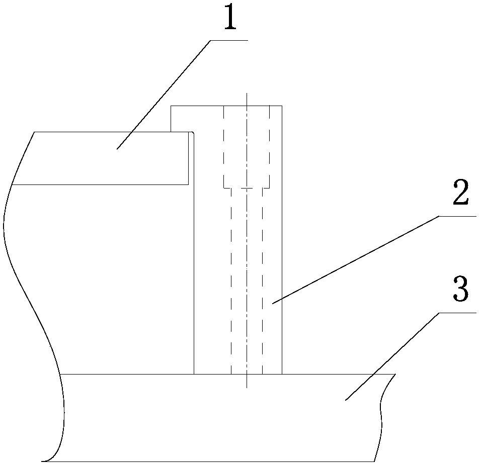
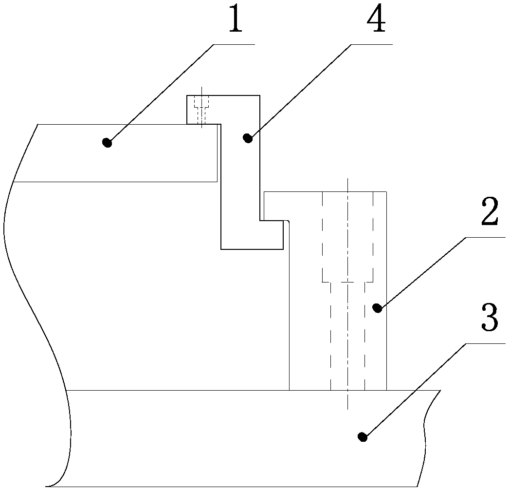
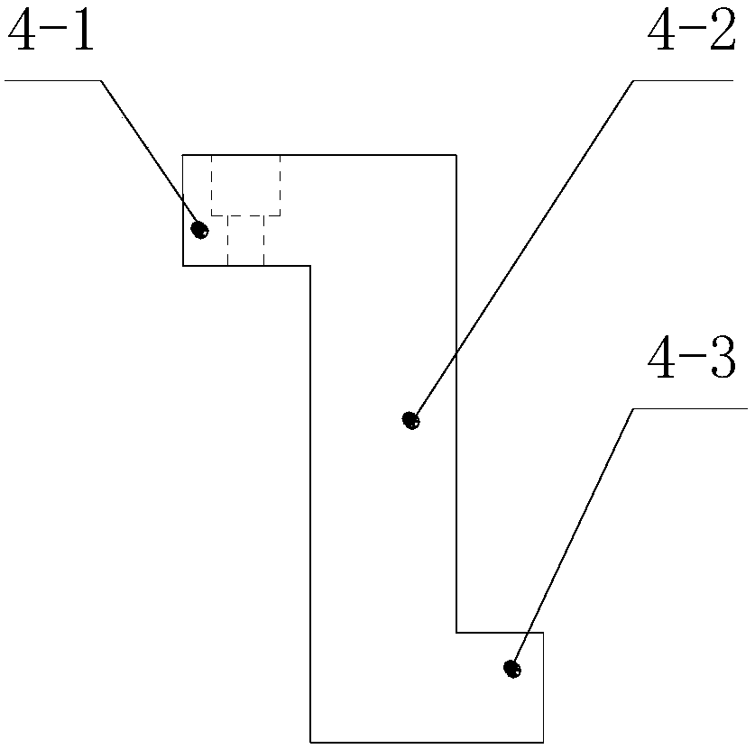
[0020] See Figure 1 to Figure 6 , a limiting structure for limiting the displacement of the floating template of the mold, including a floating template 1 and an L-shaped limiting block 2, and the L-shaped limiting block 2 includes a horizontal part A2-1 and a vertical part A2-2 perpendicular to each other, so The vertical part A2-2 of the L-shaped limiting block is fixedly connected to the fixed plate 3 or the mold base of the mold, and the horizontal part A2-1 of the L-shaped limiting block is matched with the floating template 1 to limit the The vertical displacement of the floating formwork 1 to one side, if the floating formwork 1 is an upper floating formwork, limit the downward vertical displacement of the floating form...


PUM


Abstract

The invention discloses a limiting structure for limiting displacement of a mould floating template. The limiting structure comprises a floating template and an L-type limiting block. The L-type limiting block comprises mutually perpendicular horizontal part A and vertical part A. The vertical part A is fixedly connected with a fixing plate or a mould base of a mould. The horizontal part A is matched with the floating template in a blocking mode. The limiting structure further comprises a Z-type limiting block. The Z-type limiting block comprises a vertical part B, and a horizontal part B anda horizontal part C which are positioned at two ends of the vertical part B and perpendicular to the vertical part B. The horizontal part B is fixedly connected with the floating template. The horizontal part A is matched with the horizontal part C in the blocking mode. The limiting structure is capable of improving the limiting precision, and improving a safety coefficient. The limiting structureis simple in structure, and convenient for processing and manufacturing. The processing cost is low, and the processing labor hours are less.

Description

technical field [0001] The invention relates to a mold structure, in particular to a position-limiting structure for limiting the displacement of a floating mold plate. Background technique [0002] Existing molds such as stamping dies, in order to facilitate the positioning and compression of the workpiece during the mold closing process, and in the mold opening process, in order to facilitate the separation of the workpiece and the mold, at least one of the two plates that are connected to the workpiece when the upper and lower molds are closed The plate is usually designed as a floating formwork, and the floating formwork slides up and down relative to the fixed plate of the upper and lower molds. Usually, the upper floating formwork on the upper mold is called the stripper plate, and the lower floating formwork on the lower mold is called the lower formwork. , in order to limit the displacement of the upper or lower floating formwork, a limit mechanism is often set to li...

Claims


Application Information

Patent Timeline
Patent Type & Authority Applications(China)
IPC IPC(8): B21D37/12
CPCB21D37/12
Inventor 高娜张占朋梁辰刘智元
Owner 天津市津兆机电开发有限公司
Why Eureka
Try Eureka