
Vertical oil mist collector

A collector and oil mist technology, which is applied in chemical instruments and methods, dispersed particle separation, combined devices, etc., can solve the problems of oil mist easily clogging the filter screen, primary filter congestion, and reduced filtration efficiency, so as to reduce the oil fume content. , to avoid filter congestion and slow down the effect of clogging

Pending Publication Date: 2018-06-29
浙江易德环境设备有限公司
View PDF5 Cites 5 Cited by
  • Summary
  • Abstract
  • Description
  • Claims
  • Application Information

AI Technical Summary

Problems solved by technology

[0006] The oil mist collectors of the above two structures mostly use stainless steel mesh as the primary filter. Although they have a good oil mist filtering effect, the oil mist is very easy to block the filter screen; in addition, during use, the oil mist will deposit on the At the bottom of the primary filter, the ventilation rate is reduced, which will also cause the primary filter to be blocked, resulting in a decrease in filtration efficiency;

Method used


Image

  • Vertical oil mist collector
  • Vertical oil mist collector
  • Vertical oil mist collector

Examples


Embodiment Construction

[0036] The present invention will be described in detail below in conjunction with the embodiments and accompanying drawings, but the present invention is not limited thereto.

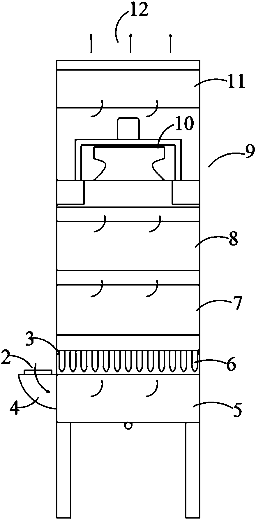
[0037] Such as Figure 1~5 The vertical oil mist collector shown includes a vertical casing 9, one side of the bottom of the casing is an air inlet 2, and the top is an air outlet 12, and the casing 9 is installed with a primary filter 7 and a middle filter in sequence from bottom to top. Efficiency filter 8, blower fan 10 and high efficiency filter 11, oil mist collection box 5 is arranged below primary effect filter 7, and oil collector 6 is installed between primary effect filter 7 and oil mist collection box 5.

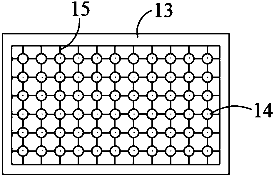
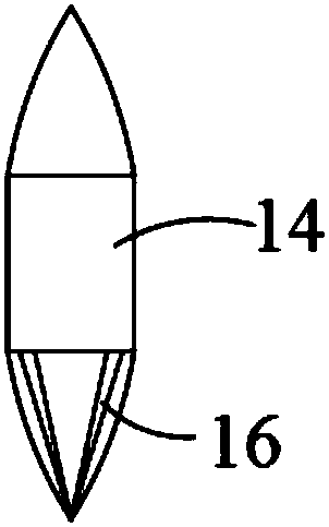
[0038] Such as figure 2 and image 3 As shown, the oil collector 6 includes an outer frame 13 and oil collecting columns 14 distributed at intervals in the outer frame 13. There is a gap between adjacent oil collecting columns 14 for oil smoke to pass through, and the bottom of each oil...


PUM


Abstract

The invention discloses a vertical oil mist collector. The vertical oil mist collector comprises a vertical shell, wherein one side of the bottom of the shell is provided with an air inlet; the top isprovided with an air outlet; a primary filter, a secondary filter, a fan and an efficient filter are arranged in the shell from bottom to top in sequence; an oil collection box is arranged below theprimary filter, wherein an oil collector is arranged between the primary filter and the oil mist collector, the oil collector comprises an outer frame and oil collection columns which are distributedin the outer frame at intervals; gaps through which oil mist can pass are formed among adjacent oil collection columns; the bottom of each oil collection columns is of an inverted conical body; the primary filter comprises a cylinder body, as well as uniform air plates, oil collection baffle plates and filtering screens which are arranged from bottom to top; vent holes are uniformly distributed onthe uniform air plates; oil falling holes are formed in the middle part; oil collection baffle plate is partitioned into an upper layer and a lower layer; the oil collection baffle plates are uniformly distributed on each layer; the oil collection baffle plates are arranged in a staggered way.

Description

technical field [0001] The invention relates to the field of environmental protection equipment, in particular to a vertical oil mist collector. Background technique [0002] The oil mist collector is an environmental protection equipment installed on various machine tools such as CNC machining centers, electric discharge processing machines, die-casting machines, and CNC lathes to collect and purify oil mist, water mist, dust and other pollutants generated during machining. . [0003] The oil mist collector can be used for oil mist and water-based mist generated by cutting oil, diesel oil and synthetic coolant as coolant during processing, spray cleaning machine, anti-rust oil spray, and coolant spray. Other large mechanical bearing lubrication process, mold processing process, exhaust cylinder, lens polishing, etc. [0004] If the oil mist cannot be removed in time, there are many potential safety hazards. Impact on the human body: In the process of CNC machine tool pro...

Claims


Application Information

Patent Timeline
Patent Type & Authority Applications(China)
IPC IPC(8): B01D50/00
CPCB01D50/20
Inventor 朱鑫洋徐成成陈栋栋
Owner 浙江易德环境设备有限公司
Learn More