Splicing type vibration-damping lead wooden frame for oil-immersed transformer
An oil-immersed transformer and vibration-absorbing lead wire technology, which can be applied to transformer/inductor coil/winding/connection, transformer/inductor noise damping, etc., can solve problems such as poor vibration-absorbing performance
- Summary
- Abstract
- Description
- Claims
- Application Information
AI Technical Summary
Problems solved by technology
Method used
Image
Examples
Embodiment 1
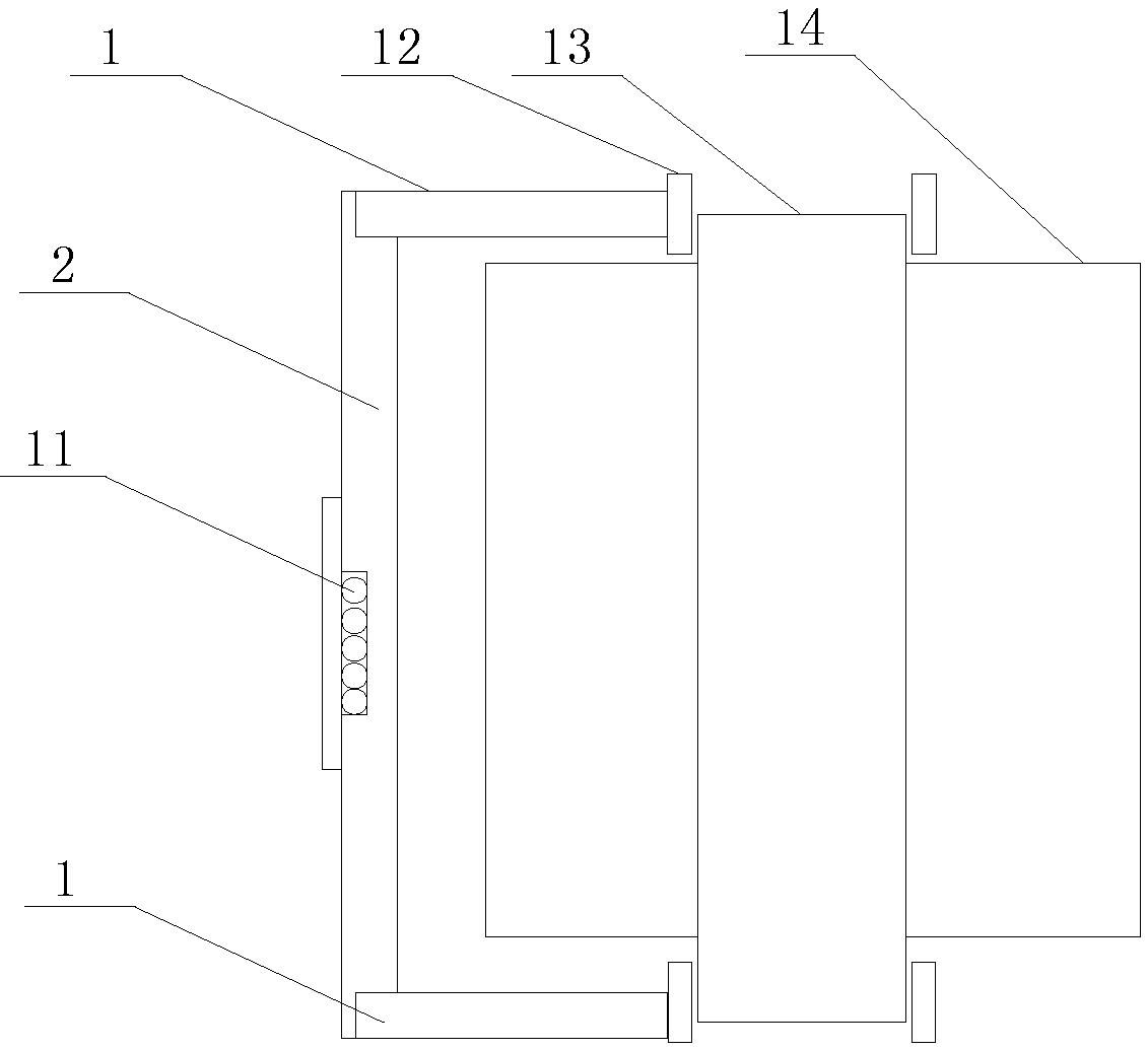
[0026] like figure 1 As shown, a splice-type vibration-damping lead wooden frame applied to the inside of an oil-immersed transformer includes a beam 1 fixed on the upper plywood 11 and lower plywood 11 of the transformer and a longitudinal beam 2 for fixing the lead wires. The longitudinal beam 2 The two ends of the two beams are respectively connected to the two beams 1, and the longitudinal beams 2 are connected to the beams 1 through a mortise and tenon structure.
[0027] The wooden frame spliced by the mortise and tenon structure can buffer and absorb the vibration of the transformer, and realize the effect of vibration reduction and noise reduction on the basis of satisfying the support function of the lead wire.
[0028] On the other hand, in the prior art, the lead wire 11 is clamped on the longitudinal beam 2, and the longitudinal beam 2 drives the lead wire 11 to swing following the vibration of the transformer. Therefore, the joint of the lead wire 11 bears a rel...
Embodiment 2
[0030] Further improvement on the basis of Embodiment 1, there is a set gap between the tenon head and the tenon groove in the mortise and tenon structure, and the gap is filled with an elastic sealant after curing.
[0031] According to the specifications of the commonly used 180kVA transformer at present, the size of the gap is usually set at 2-4mm. If the gap is too small, it is difficult to fill the sealant completely; if the gap is too large, the strength of the wooden frame cannot meet the use requirements. For transformers of other specifications, the size of the gap can be set as appropriate according to the specifications of the wooden frame.
[0032] The gap is filled with a cured elastic sealant, which can enhance the firmness of the connection. At the same time, due to the cured elastic, when the vibration force is applied, when the tenon moves with the direction of the force, the cured sealing When the rubber is extruded, the tenon is subjected to reverse extrusi...
Embodiment 3
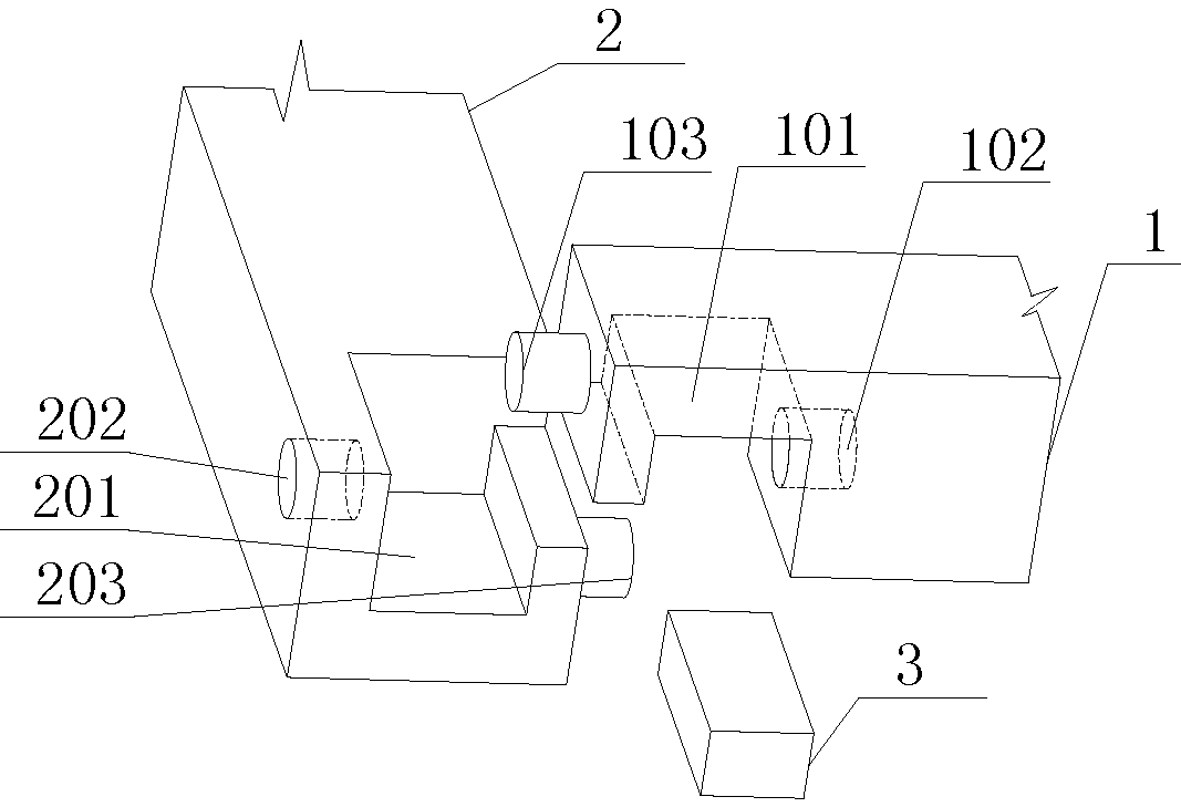
[0035] like figure 2 As shown, further improvement on the basis of Embodiment 1, the mortise and tenon structure at the end of the crossbeam 1 includes: a crossbeam chute 101, a crossbeam tenon 103 and a crossbeam mortise 102 respectively located on both sides of the crossbeam chute 101; The mortise and tenon structure of the longitudinal beam 2 includes: a longitudinal beam chute 201, a longitudinal beam tenon 203 and a longitudinal beam tenon 202 respectively located on both sides of the longitudinal beam chute 201; Described beam mortise 102 cooperates with longitudinal beam tenon 203, as image 3 As shown, the beam slot 101 and the longitudinal beam slot 201 form a slot hole 15 for inserting the wedge block 3 .
[0036] Wherein, the cross-sectional shape of the beam tenon 103 and the longitudinal beam tenon 203 is not limited to figure 2 Circular as shown, other shapes such as triangular, rectangular, elliptical or other geometric shapes are also possible.
[0037] In...
PUM
 Abstract
Description
Claims
Application Information
 - R&D
- Intellectual Property
- Life Sciences
- Materials
- Tech Scout
- Unparalleled Data Quality
- Higher Quality Content
- 60% Fewer Hallucinations
Browse by: Latest US Patents, China's latest patents, Technical Efficacy Thesaurus, Application Domain, Technology Topic, Popular Technical Reports.
© 2025 PatSnap. All rights reserved.Legal|Privacy policy|Modern Slavery Act Transparency Statement|Sitemap|About US| Contact US: help@patsnap.com


