Sand drying device for building

A drying device and a technology for building sand, applied in the field of construction engineering, can solve the problems of low drying efficiency and uneven heating, and achieve the effects of saving time and improving efficiency

Inactive Publication Date: 2018-06-26
重庆吉邦装饰工程有限公司
View PDF5 Cites 2 Cited by
  • Summary
  • Abstract
  • Description
  • Claims
  • Application Information

AI Technical Summary

Problems solved by technology

[0004] The purpose of the present invention is to provide a construction sand drying device to solve the problem of low drying efficiency caused by uneven heating during drying

Method used


Image

  • Sand drying device for building
  • Sand drying device for building

Examples


Embodiment Construction

[0019] The following is further described in detail through specific implementation methods:

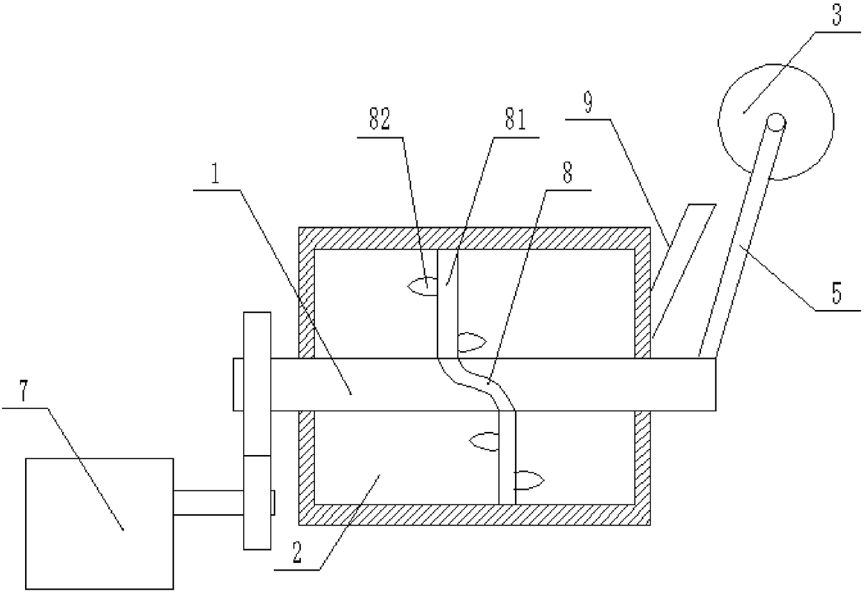
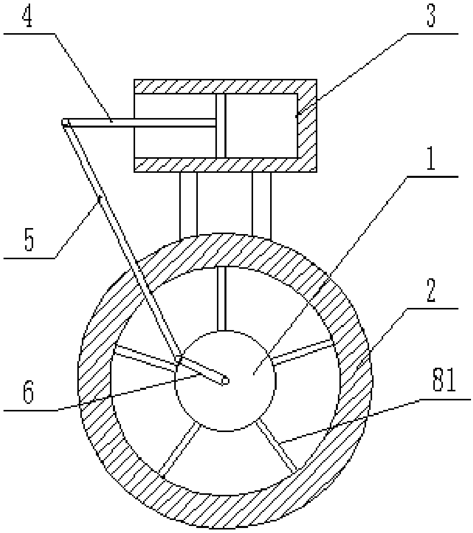
[0020] The reference signs in the drawings of the description include: rotating shaft 1, drying cylinder 2, piston barrel 3, piston rod 4, first connecting rod 5, second connecting rod 6, rotating motor 7, spiral groove 8, column rod 81, Stirring blade 82, delivery pipe 9.

[0021] Such as figure 1 As shown, the sand drying device for construction includes a frame on which a piston barrel 3 and a drying cylinder 2 located below the piston barrel 3 are arranged. The middle parts of the left and right ends of the drying cylinder 2 are provided with mounting holes. , the mounting hole is connected with a rotating shaft 1, and a rotating motor 7 is also fixed on the frame. The output shaft of the rotating motor 7 is connected with a driving gear, and the left end of the rotating shaft 1 is provided with a driven gear meshing with the driving gear. There is an air intake slot, the lengt...


PUM


Abstract

The invention belongs to the field of construction engineering, and particularly discloses a sand drying device for building. The sand drying device for the building comprises a machine frame, a piston barrel and a drying cylinder, wherein the piston barrel is arranged on the machine frame, and the drying cylinder is positioned below the piston barrel; a rotating shaft is further rotationally connected to the machine frame, and the rotating shaft penetrates through the two end surfaces of the drying cylinder; the piston barrel is fixedly connected to the machine frame, an electric heating wireis wound around the outer wall of the piston barrel, a guide wire is connected to the electric heating wire, the guide wire is connected with a first electrode piece, the first electrode piece is arranged at one opening end of the piston barrel, and a piston is slidably connected in the piston barrel; the sand drying device for the building further comprises a piston rod, a first connecting rod and a second connecting rod which are hinged in sequence, wherein a power supply is arranged on the piston rod, and a second electrode piece is arranged on the power supply; and an air inlet groove isformed in the rotating shaft, a through hole communicates with the air inlet groove is formed in the outer wall of the rotating shaft, and an air outlet hole and an air inlet hole are formed in the side wall of the piston barrel. By the adoption of the scheme, gravel raw materials can be separated while being dried, so that time is saved, and efficiency is improved.

Description

technical field [0001] The invention belongs to the field of construction engineering and specifically discloses a construction sand drying device. Background technique [0002] In the process of concrete production, a large amount of sand and gravel and various additives are needed. The raw materials of sand and gravel are generally obtained from rivers and other places. To determine the quality of the concrete produced during the use process, the sand and gravel raw materials need to be dried, and the sand and stones should be screened after drying, so that the ratio of sand and stones can be adjusted for subsequent use. [0003] The sand and gravel drying device in the prior art includes a drying cylinder, the side wall of the drying cylinder is wound with a heating wire, and the sand and gravel in the drying cylinder are dried by using the heat generated after the heating wire is energized. The above-mentioned device has the following problems: the sand and gravel near ...

Claims


Application Information

Patent Timeline
Patent Type & Authority Applications(China)
IPC IPC(8): F26B11/06F26B21/00F26B25/04
CPCF26B11/0486F26B21/001F26B21/004F26B25/04F26B2200/14
Inventor 王宏伟
Owner 重庆吉邦装饰工程有限公司
Why Eureka
Try Eureka