High-strength space steel structure joint and installation method thereof

A steel structure, high-strength technology, applied in building construction, construction, and building materials processing, etc., can solve the problems of spatial steel structure strength, low strength and construction efficiency, and construction and installation methods affecting overall quality and construction efficiency.

Inactive Publication Date: 2018-06-26
新昌县丽晶工业产品设计有限公司
View PDF0 Cites 4 Cited by
  • Summary
  • Abstract
  • Description
  • Claims
  • Application Information

AI Technical Summary

Problems solved by technology

[0002] Spatial steel structure refers to a steel structure system with a large space span. Several nodes are connected by several rods. Due to the large number of rods required, usually tens of thousands are required, the structure of the nodes and the connection form with the rods will affect the entire space. The strength of the steel structure will be affected, and the construction and installation method will also directly affect the overall quality and construction efficiency
[0003] The existing space steel structure generally directly connects the ends of the rods and the nodes through fasteners, and the strength and construction efficiency are low, so it is necessary to improve

Method used


Image

  • High-strength space steel structure joint and installation method thereof
  • High-strength space steel structure joint and installation method thereof
  • High-strength space steel structure joint and installation method thereof

Examples


Embodiment Construction

[0046] The following are specific embodiments of the present invention and in conjunction with the accompanying drawings, the technical solutions of the present invention are further described, but the present invention is not limited to these embodiments.

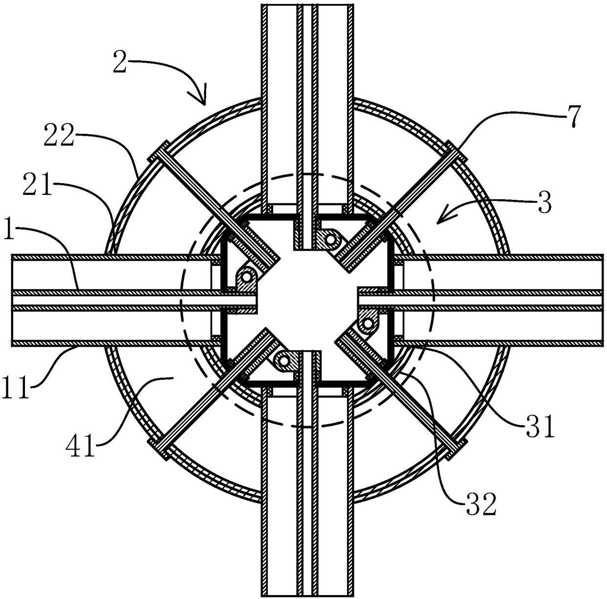
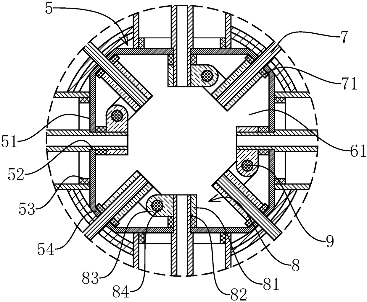
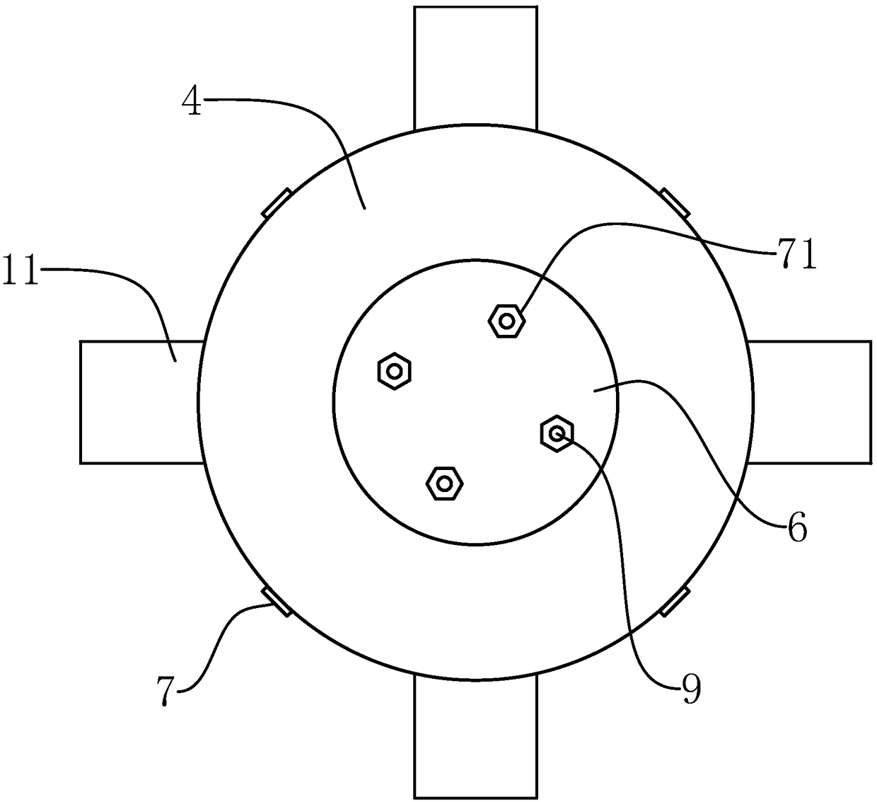
[0047] Such as Figure 1-7 As shown, a high-strength space steel structure node of the present invention includes a connecting pipe 1 and a support pipe 11 arranged coaxially and both of which are of a circular tubular structure, and an outer support cylinder which is arranged coaxially and is of a cylindrical structure 2 and the inner support tube 3 also include a parallel annular plate-shaped upper sleeve plate 4 and a lower sleeve plate 41, the outer edge and inner edge of the upper sleeve plate 4 are respectively connected with the inner wall of the top end of the outer support tube 2 and the inner support The outer wall at the top of the cylinder 3 is fixed, the outer edge and the inner edge of the lower sleeve plate ...


PUM


Abstract

The invention provides a high-strength space steel structure joint and an installation method thereof, and belongs to the field of space steel structures. According to the high-strength space steel structure joint, the problem that the strength of existing space steel structure joint is low is solved. The high-strength space steel structure joint comprises a connecting pipe, a support pipe, an external support cylinder, an inner support cylinder, an upper sleeving plate, a lower sleeving plate, a connecting cylinder, an upper sealing plate and a lower sealing plate. The connecting cylinder includes connecting plates and fixed plates. The external arc surfaces of the fixed plates are fixed to the inner wall of the inner support cylinder. Outer sleeving holes are formed in the external support cylinder in the circumferential direction. Inner sleeving holes are distributed on the inner support cylinder in the circumferential direction. Connecting holes are formed in the connecting plates.The support pipe penetrates through the outer sleeving holes and the inner sleeving holes. The end of the support pipe is connected to the outer side surfaces of the connecting plates in a welding mode. The connecting pipe penetrates through the connecting holes and is connected with screw caps in a threaded mode. The upper sealing plate and the lower sealing plate are fixed on the two ends of the connecting cylinder. The connecting cylinder, the upper sealing plate and the lower sealing plate are encircled to form a pouring area. Concrete mortar is poured in the pouring area. The joint is suitable for on-site assembly, and the stress is clearer.

Description

technical field [0001] The invention belongs to the technical field of space steel structures, and relates to a high-strength space steel structure node and an installation method thereof. Background technique [0002] Spatial steel structure refers to a steel structure system with a large space span. Several nodes are connected by several rods. Due to the large number of rods required, usually tens of thousands are required, the structure of the nodes and the connection form with the rods will affect the entire space. The strength of the steel structure will be affected, and the construction and installation method will also directly affect the overall quality and construction efficiency. [0003] The existing space steel structure generally directly connects the end of the bar and the node through the fastener, and the strength and construction efficiency are low, so it is necessary to improve it. Contents of the invention [0004] The purpose of the present invention i...

Claims


Application Information

Patent Timeline
IPC IPC(8): E04B1/24E04G21/14
CPCE04B1/2403E04B2001/2406E04G21/14
Inventor 王斌辉
Owner 新昌县丽晶工业产品设计有限公司
Why Eureka
Try Eureka