Durable centrifugal regenerator

A centrifugal regenerator and durable technology, applied in the field of sand treatment, can solve the problems of damage to the centrifugal disc, affecting the service life of the centrifugal regenerator, etc., to achieve the effect of ensuring quality, prolonging life, and high fatigue limit

Active Publication Date: 2018-06-26
青岛胶东机械制造有限公司
View PDF7 Cites 0 Cited by
  • Summary
  • Abstract
  • Description
  • Claims
  • Application Information

AI Technical Summary

Problems solved by technology

[0004] After the above-mentioned centrifugal regenerator has been used for a long time, the sand will continuously collide with the centrifugal disc, which will easily cause damage to the centrifugal disc and affect the service life of the centrifugal regenerator.

Method used


Image

  • Durable centrifugal regenerator
  • Durable centrifugal regenerator
  • Durable centrifugal regenerator

Examples


Embodiment

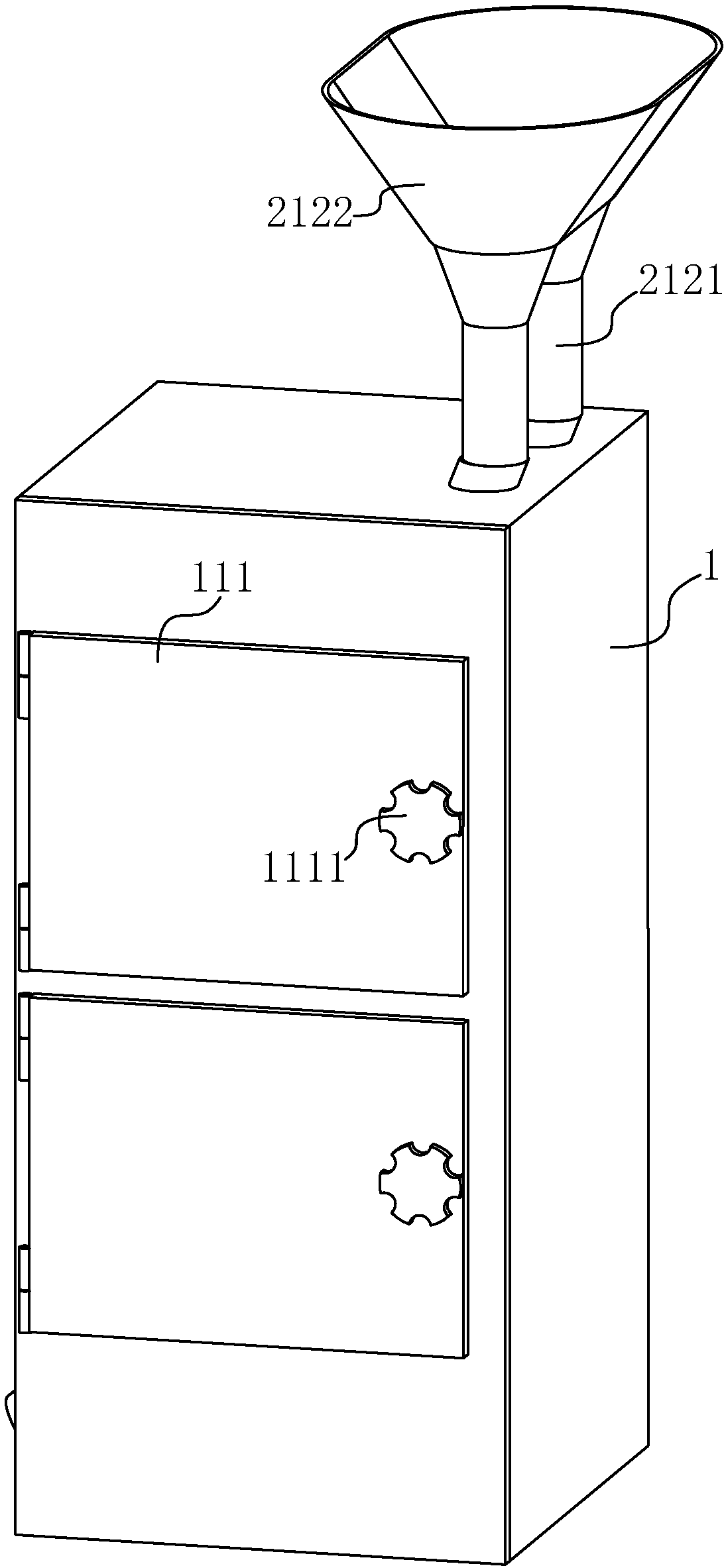
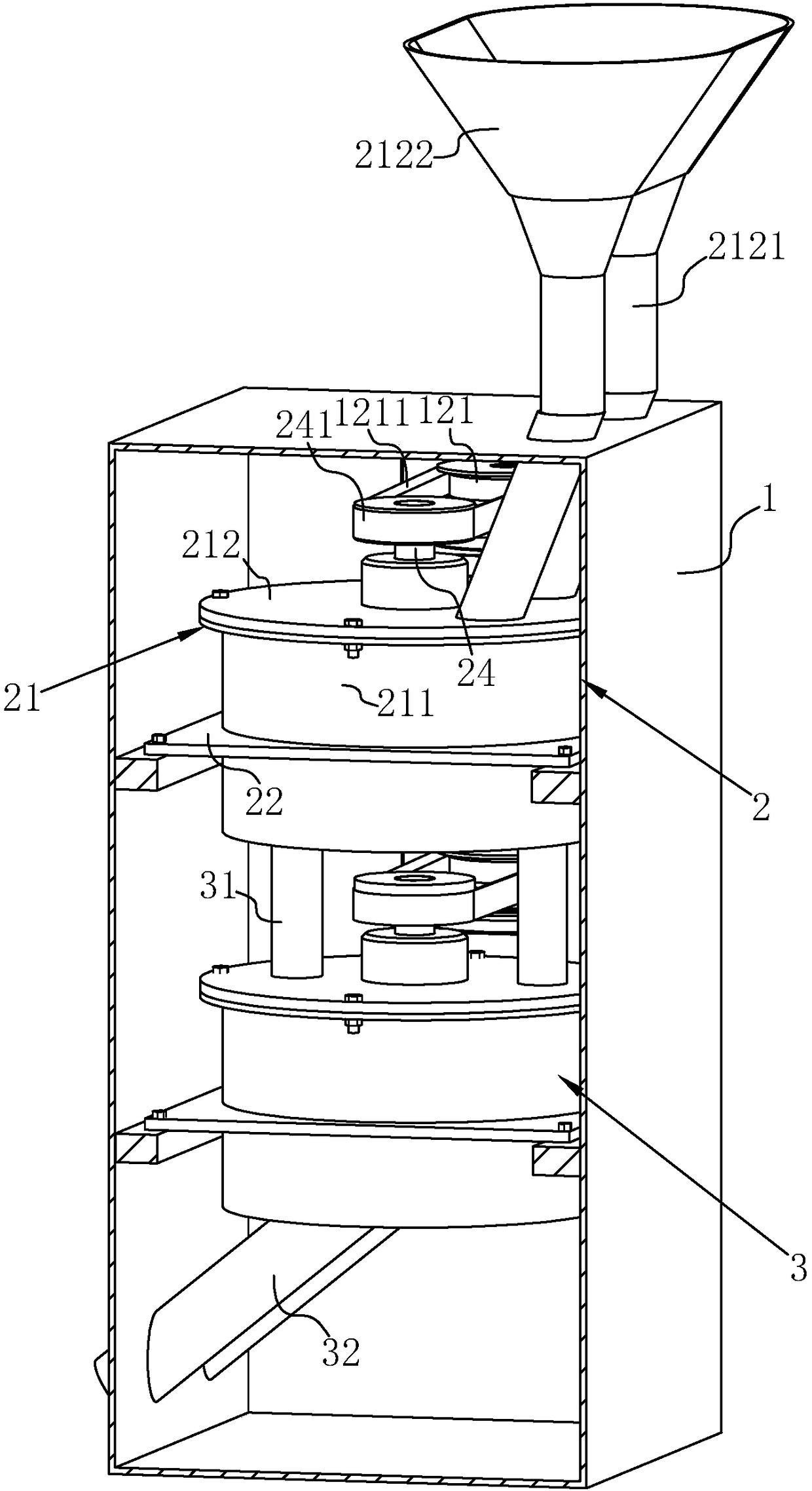
[0034] Example: A durable centrifugal regenerator incorporating figure 1 and figure 2 , including a housing 1 placed on the ground, a centrifugal regeneration device 2 connected to the housing 1, a secondary regeneration device 3 connected to the housing 1 and located below the centrifugal regeneration device 2, and the secondary regeneration device 3 is connected to the centrifugal regeneration device 2 times.

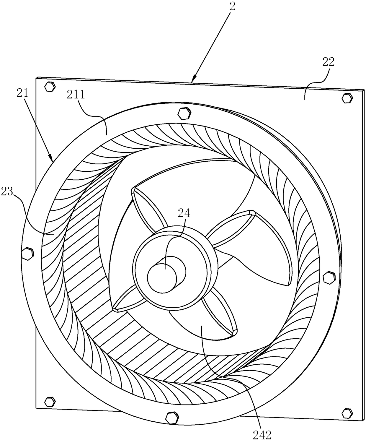
[0035] combine figure 2 and image 3 The centrifugal regeneration device 2 includes a cover body 21 connected to the casing 1 and a rotating shaft 24 rotatably connected to the middle of the cover body 21. The rotating shaft 24 is fixedly connected with a pulley 241, and the rotating shaft 24 protrudes outside the cover body 21 and the pulley 241 is fixedly connected. The part protruding from the cover body 21 on the rotating shaft 24 . Outside the housing 1 at the corresponding pulley 241 position, a motor 12 is fixedly connected (see Figure 4 ), the driving ...


PUM


Abstract

The invention discloses a durable centrifugal regenerator. According to the technical scheme, the durable centrifugal regenerator is mainly characterized by comprising an outer shell arranged on the ground, and a centrifugal regeneration device connected into the outer shell; the centrifugal regeneration device comprises a cover body fixedly connected into the outer shell, a plurality of arc-shaped baffles which are fixedly connected into the cover body, attach to one another and are arranged in a circular array, a rotary shaft rotationally connected to the middle of the cover body, and a plurality of fan blades which are fixedly connected to the rotary shaft and arranged in a circular array; and impact force of sand to the cover body is reduced, and the service life of the centrifugal regenerator is prolonged.

Description

technical field [0001] The invention relates to the field of sand treatment, in particular to a durable centrifugal regenerator. Background technique [0002] When using sand, it is usually necessary to regenerate the unprocessed sand using a centrifugal regenerator to remove the inert film on the surface of the sand before continuing to process it. [0003] Existing reference can be made to the Chinese patent whose authorized announcement number is CN203843100U, which discloses a two-stage resin sand centrifugal regenerator in series, with a ring-shaped sand collection cone seat on the upper inner wall of each set of body. The sand collecting cone is fixed on the cone seat, a centrifugal disc is arranged under the sand collecting cone, and a retaining ring is arranged above the centrifugal disc. The positioning slots are plugged and connected together. There are oil inlet and outlet holes on the outer wall of the bearing between the upper and lower bearings. The drive pull...

Claims


Application Information

Patent Timeline
Patent Type & Authority Applications(China)
IPC IPC(8): B22C5/02
Inventor 孙锟
Owner 青岛胶东机械制造有限公司
Why Eureka
Try Eureka