High-speed mould threaded core cooling structure

A threaded core and cooling structure technology, applied to threaded products, household appliances, other household appliances, etc., can solve the problems of inner plug pits, prolonged cycle, easy air leakage, etc., to facilitate installation and disassembly, production. The effect of improved efficiency and faster molding cycle

Inactive Publication Date: 2018-06-22
SUZHOU LIANKAI PRECISION MOLD
View PDF8 Cites 0 Cited by
  • Summary
  • Abstract
  • Description
  • Claims
  • Application Information

AI Technical Summary

Problems solved by technology

[0002] The current high-speed mold thread core cooling structure is as follows: Figure 1 ~ Figure 2 As shown, the cooling water enters the inner core through the cooling circuit to cool the inner core. The outer surface of the inner core is in contact with the inner hole of the threaded core, and the inner core takes away the threaded core through the form of heat transfer. In order to meet the customer's requirements, the cooling cycle can only be prolonged, so that the production efficiency will be relatively low. If the cooling of the forming part is not good, the produced product will easily have inner plug pits. , Pitting, such a product will lead to poor airtightness and easy air leakage

Method used


Image

  • High-speed mould threaded core cooling structure
  • High-speed mould threaded core cooling structure
  • High-speed mould threaded core cooling structure

Examples


Embodiment Construction

[0021] In order to make the present invention clearer and easier to understand, a preferred embodiment is described with reference to the accompanying drawings.

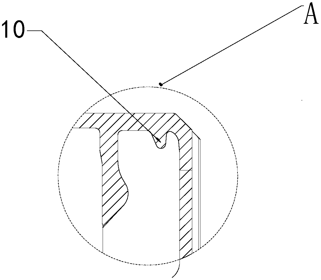
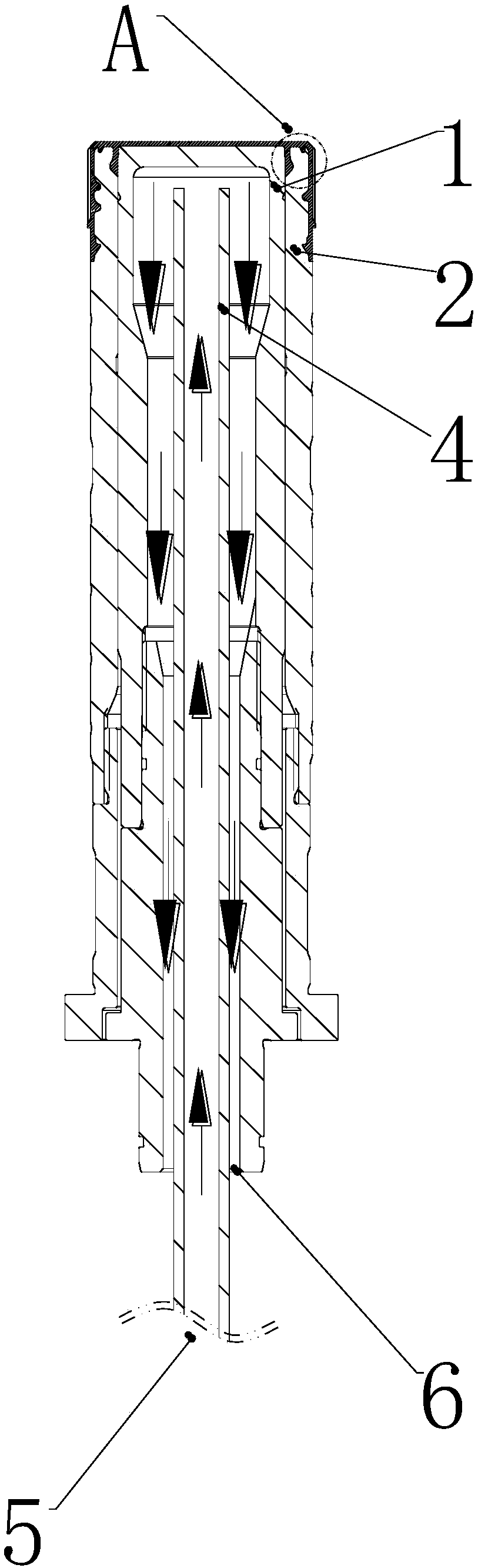
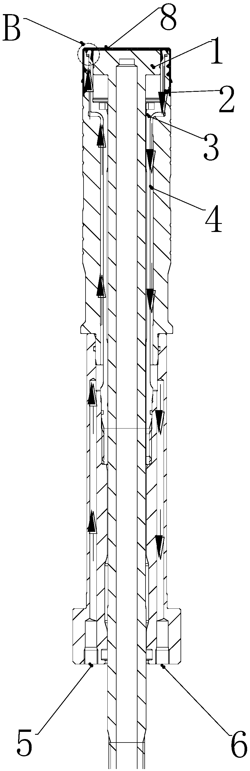
[0022] figure 2 As a preferred embodiment of the present invention, a high-speed mold thread core cooling structure includes an inner core 1 and a thread core 2, the thread core 2 is provided with a hollow cavity, and an insert 3 is installed in the hollow cavity , There is a gap between the insert 3 and the inner wall of the hollow cavity, and the gap forms a cooling circuit 4 .

[0023] Such as Figure 5 As shown, the cooling circuits 4 are evenly distributed on the outer peripheral wall of the insert 3 . The cooling circuit 4 is provided with a water inlet 5 and a water outlet 6 at one end of the insert 3 .

[0024] By adjusting the structure of the parts, the cooling of the waterway is closer to the product 8, the cooling is direct and effective, thereby reducing the cooling cycle of the entire mold, and the ...


PUM

PropertyMeasurementUnit
thermal conductivityaaaaaaaaaa

Abstract

The invention discloses a high-speed mould threaded core cooling structure which comprises an internal core and a threaded core. The high-speed mould threaded core cooling structure is characterized in that the threaded core is provided with a hollow cavity; an insert is arranged in the hollow cavity; a gap is reserved between the insert and the inner wall of the hollow cavity; and a cooling loopis formed by the gap. According to the high-speed mould threaded core cooling structure, the cooling loop is more balanced, the cooling on the forming part of a product is more direct and effective, the production efficiency is improved and the produced product meets the all requirements.

Description

technical field [0001] The invention relates to the technical field of molds, in particular to a cooling structure for threaded cores of high-speed molds. Background technique [0002] The current high-speed mold thread core cooling structure is as follows: Figure 1 ~ Figure 2 As shown, the cooling water enters the inner core through the cooling circuit to cool the inner core. The outer surface of the inner core is in contact with the inner hole of the threaded core, and the inner core takes away the threaded core through the form of heat transfer. In order to meet the customer's requirements, the cooling cycle can only be prolonged, so that the production efficiency will be relatively low. If the cooling of the forming part is not good, the produced product will easily have inner plug pits. , Pitting, such products will lead to poor airtightness and easy air leakage. Contents of the invention [0003] Aiming at the deficiencies of the existing technology, the present in...

Claims


Application Information

Patent Timeline
Patent Type & Authority Applications(China)
IPC IPC(8): B29C45/73B29C33/04B29C33/76B29L1/00
CPCB29C33/04B29C33/76B29C45/7312B29L2001/00
Inventor 曾智
Owner SUZHOU LIANKAI PRECISION MOLD
Why Eureka
Try Eureka