Universal cabinet lock

A general-purpose machine and cabinet lock technology, applied in the field of locks, can solve problems affecting the lock body, complex structure of the lock cylinder, pollution and blockage of the lock cylinder, etc., to achieve the effect of improving the sealing effect, avoiding dirt pollution, and prolonging the service life

Pending Publication Date: 2018-06-19
ZHEJIANG MAKEPOWER ELECTRONICS
View PDF9 Cites 4 Cited by
  • Summary
  • Abstract
  • Description
  • Claims
  • Application Information

AI Technical Summary

Problems solved by technology

According to customer requirements, there are various unlocking methods for cabinet locks. In addition to conventional mechanical locks, electromagnetic locks or motor locks that can be remotely controlled are usually required. However, the existing cabinet locks are difficult to combine with multiple unlocking methods and are universal. The performance is poor. Further, it is difficult to combine the mechanical lock with other electronically controlled locks. The frequent opening and closing, rotation, and impact of the rotating handle will reduce the life of the lock cylinder and affect the stability of the parts of the lock body. Some lock cylinders have complex structures, high matching size requirements, and cumbersome assembly and debugging, which directly increase the direct and indirect costs of the product, and the existing cabinet locks, the dust cov

Method used


Image

  • Universal cabinet lock
  • Universal cabinet lock
  • Universal cabinet lock

Examples


Embodiment approach

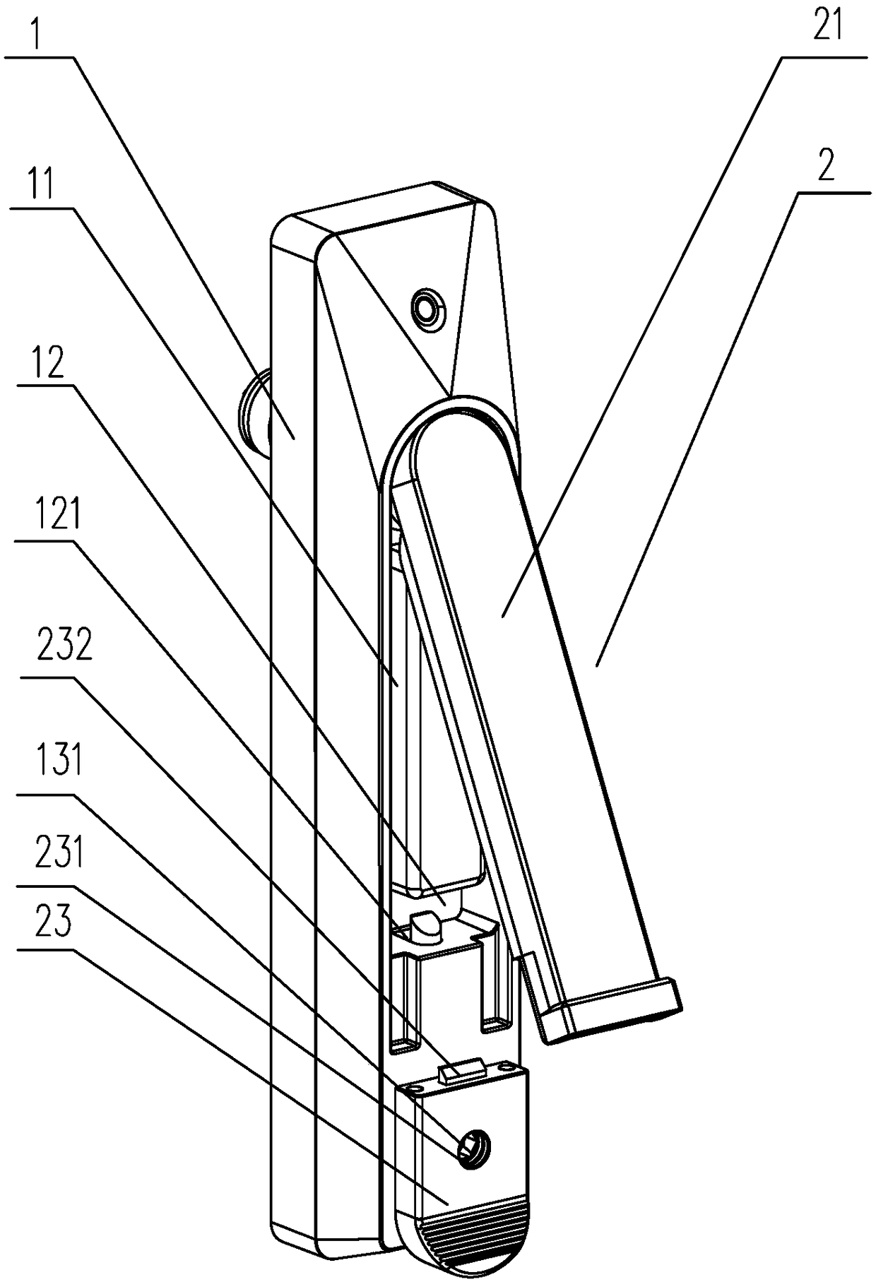
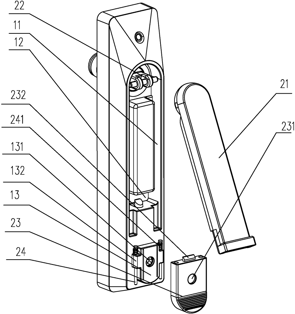
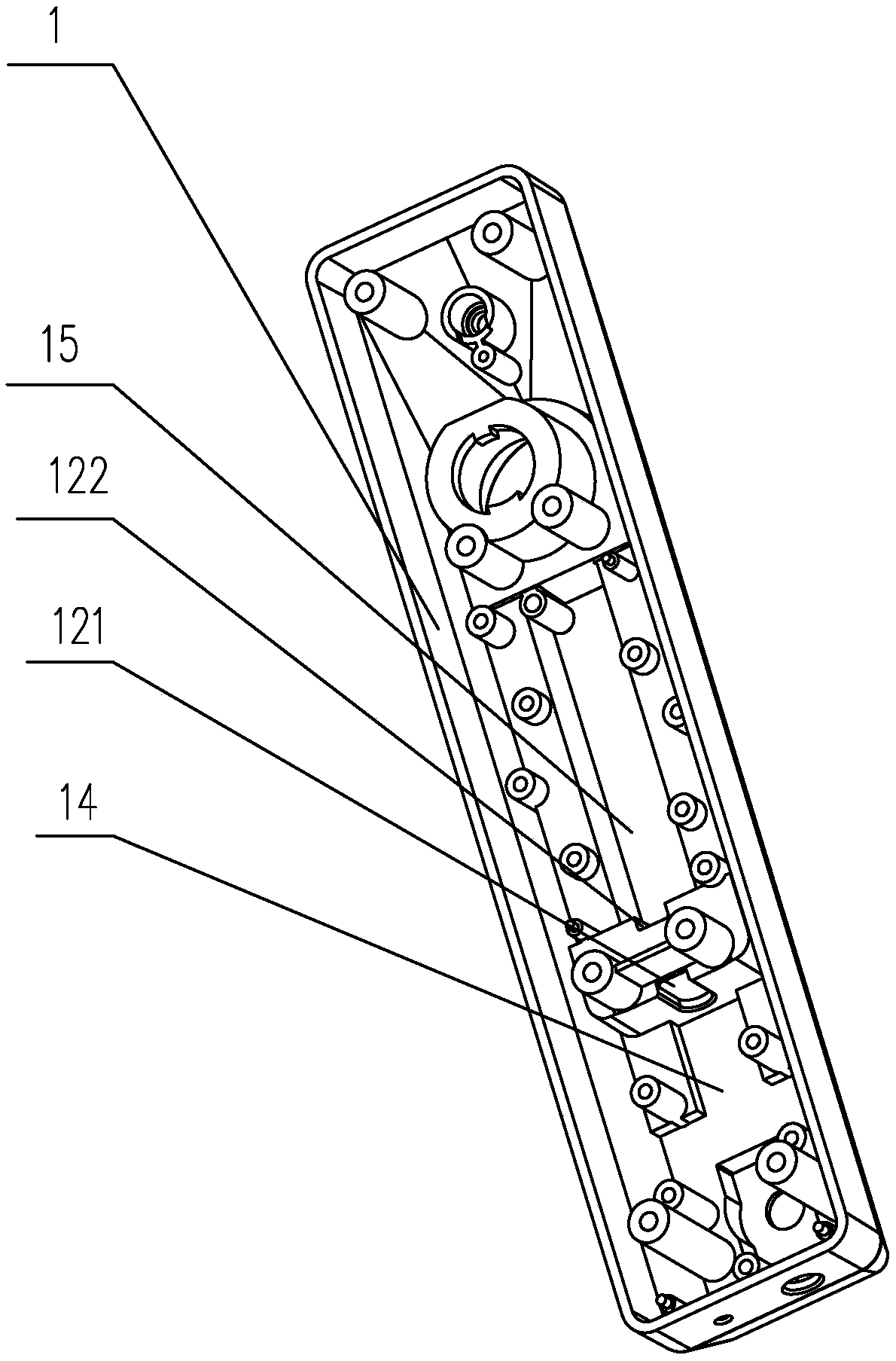
[0035] Depend on Figure 1 to Figure 9 It can be seen that the first embodiment of the present invention discloses a universal cabinet lock, which includes a mounting base 1 and a handle 2, the handle 2 includes a handle 21 and a rotating seat 22, and the rotating seat 22 is rotatably arranged on the mounting base 1, the front end surface of the mounting base 1 is provided with a handle accommodating groove 11 for accommodating the handle 21, the handle 21 is hinged with the rotating seat 22, and the handle 21 and the rotating seat 22 are also provided with a torsion spring for ejecting the grip 21 from the grip accommodating groove 11, and a push cover 23 for restricting the ejection of the grip 21 is also arranged on the front end of the mounting base 1. The mounting base 1 is also provided with a first mounting groove 14 for installing an electromagnetic lock and a second mounting groove 15 for installing a motor lock 4, and the first mounting groove 14 is arranged on the m...


PUM


Abstract

The invention discloses a universal cabinet lock. The universal cabinet lock comprises an installing base and a lever handle. The lever handle comprises a holding handle. The installing base is provided with a holding handle containing groove. A push cover is further arranged on the front end face of the installing base. The installing base is provided with a first installing groove and a second installing groove. A mechanical lock is arranged in the first installing groove and comprises a lock cylinder. A key hole is formed in the front end face of the installing base. The push cover is arranged on the key hole in a sliding manner. A locking groove is formed in the holding handle containing groove. The holding handle extends into the locking groove to form a fixing protruding column whichis provided with a lock hole. A first pin hole and a second pin hole are formed in the inner wall of the locking groove, the first pin hole communicates with the first installing groove, and the second pin hole communicates with the second installing groove. The universal cabinet lock can be matched with an electromagnetic lock, a motor lock and a mechanical lock. The structure is simple, meanwhile, a dustproof structure on the lock face is reasonable, and the situation that mistaken unlocking under the unmanned condition happens, and the door opening holding handle pops up can be prevented.

Description

technical field [0001] The invention relates to the technical field of locks, in particular to a general cabinet lock. Background technique [0002] As people's demand for networks increases day by day, operators are also required to develop and cover networks more and more deeply. More and more outdoor sites are gradually expanding from pure marginal networks to urban areas and road coverage, so as to effectively solve the problems of network coverage blind spots and alleviate regional communication pressure. The construction of an outdoor network requires the use of outdoor cabinets. At present, the anti-theft performance, protection performance and flexibility of outdoor cabinets are increasingly required. According to customer requirements, there are various unlocking methods for cabinet locks. In addition to conventional mechanical locks, electromagnetic locks or motor locks that can be remotely controlled are usually required. However, the existing cabinet locks are d...

Claims


Application Information

Patent Timeline
IPC IPC(8): E05B47/00E05B47/02E05B65/02E05B65/52E05B17/18E05B17/20
CPCE05B17/186E05B17/20E05B47/0002E05B47/0012E05B47/026E05B65/02
Inventor 张焱黄勇达陈琪锋余晓杰孙铿锵胡乾普陈俊军邹晓巍夏景仲刘景斌
Owner ZHEJIANG MAKEPOWER ELECTRONICS
Why Eureka
Try Eureka