Multi-module type photovoltaic power generation installing support
A technology for photovoltaic power generation and mounting brackets, applied in photovoltaic power generation, photovoltaic module support structures, photovoltaic modules, etc., can solve problems such as inconvenient operation, reduce the demand for driving force and pulling force of telescopic rods, facilitate handling operations, and reduce materials required effect
- Summary
- Abstract
- Description
- Claims
- Application Information
AI Technical Summary
Problems solved by technology
Method used
Image
Examples
Embodiment 1
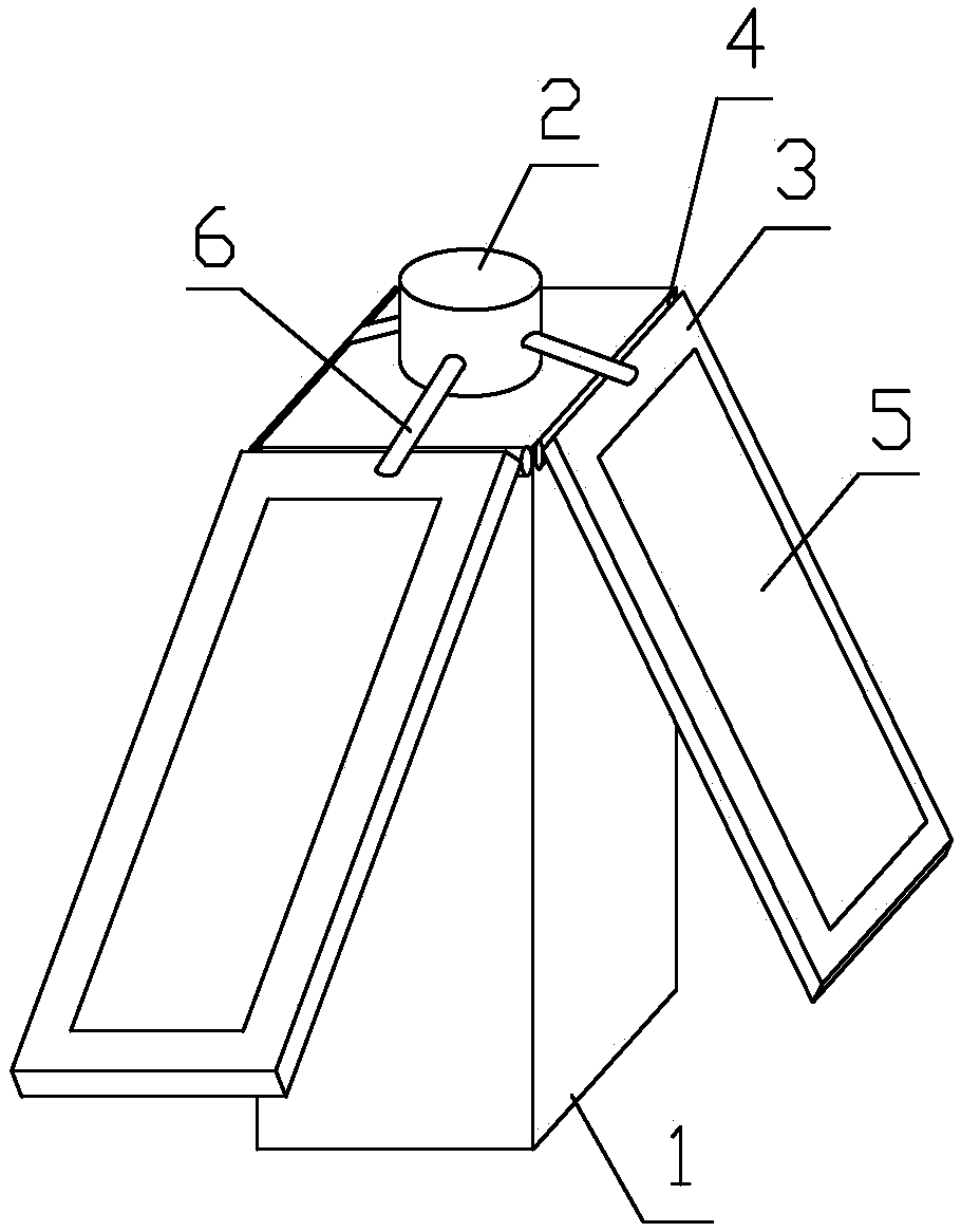
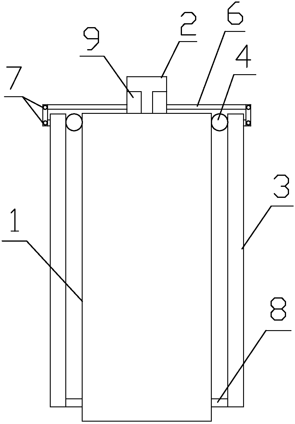
[0027] The multi-module photovoltaic power generation installation bracket includes a fixed column 1, and the radial cross section of the fixed column 1 is a regular polygonal structure; There is a mounting plate 3, the lower plate surface of one end of the long axis direction of the mounting plate 3 is connected with the side wall near the top of the fixed column 1 through the rotating shaft 4, and the axial direction of the rotating shaft 4 is parallel to the side of the fixed column 1 where it is located. The upper plate is provided with a photovoltaic power generation panel 5; it also includes a number of telescopic rods 6, one axial end of which is fixed in the installation housing 2, and the other end is connected to the upper surface of the long axis of the installation plate 3 through a universal joint. The joint 7 is connected; through the contraction or elongation of the telescopic rod 6, the mounting plate 3 is pulled to rotate upwards with the rotating shaft 4 as th...
Embodiment 2
[0029] Further improvement on the basis of Embodiment 1, a return spring is sleeved on the rotating shaft 4. When the return spring is in a natural state, the direction of the plate surface of the mounting plate 3 is perpendicular to the side of the fixed column 1 where it is located. When the mounting plate 3 rotates downward When the other end in the direction of the long axis approaches the side wall of the fixed column 1, the return spring is compressed. A rubber buffer pad 8 is provided on the lower plate surface of the other end of the axial direction away from the rotating shaft 4 on the mounting plate 3. When the mounting plate 3 rotates downward until the plate surface of the mounting plate 3 is parallel to the side of the fixed column 1, the rubber buffer pad 8 is in contact with the side of the corresponding fixed column 1.
[0030] Example 2
[0031] Further improvement on the basis of Embodiment 1, the bottom of the fixed column 1 is provided with several univers...
PUM
 Abstract
Description
Claims
Application Information
 - R&D
- Intellectual Property
- Life Sciences
- Materials
- Tech Scout
- Unparalleled Data Quality
- Higher Quality Content
- 60% Fewer Hallucinations
Browse by: Latest US Patents, China's latest patents, Technical Efficacy Thesaurus, Application Domain, Technology Topic, Popular Technical Reports.
© 2025 PatSnap. All rights reserved.Legal|Privacy policy|Modern Slavery Act Transparency Statement|Sitemap|About US| Contact US: help@patsnap.com


