Touch screen laser spliced pattern structure and etching wiring method thereof

A technology of etching lines and touch screens, which is applied in the field of laser splicing pattern structure and etching wiring of touch screens. It can solve problems such as short circuit and limited laser distance at one time, and achieve the effects of ensuring splicing accuracy, avoiding splicing deviation, and saving etching and wiring time.

Active Publication Date: 2018-06-15
ZHANGJIAGANG KANGDE XIN OPTRONICS MATERIAL
View PDF6 Cites 1 Cited by
  • Summary
  • Abstract
  • Description
  • Claims
  • Application Information

AI Technical Summary

Problems solved by technology

The ITO pattern unit in the touch screen adopts the laser process, but the distance of the laser once is limited and needs to be spliced, so it is impossible to realize such Figure 1C Ideal etched wire routing
There is a problem of splicing deviation in the direct splicing of oblique lines and oblique lines by laser machines, which will cause local short circuits

Method used


Image

  • Touch screen laser spliced pattern structure and etching wiring method thereof
  • Touch screen laser spliced pattern structure and etching wiring method thereof
  • Touch screen laser spliced pattern structure and etching wiring method thereof

Examples


Embodiment 1

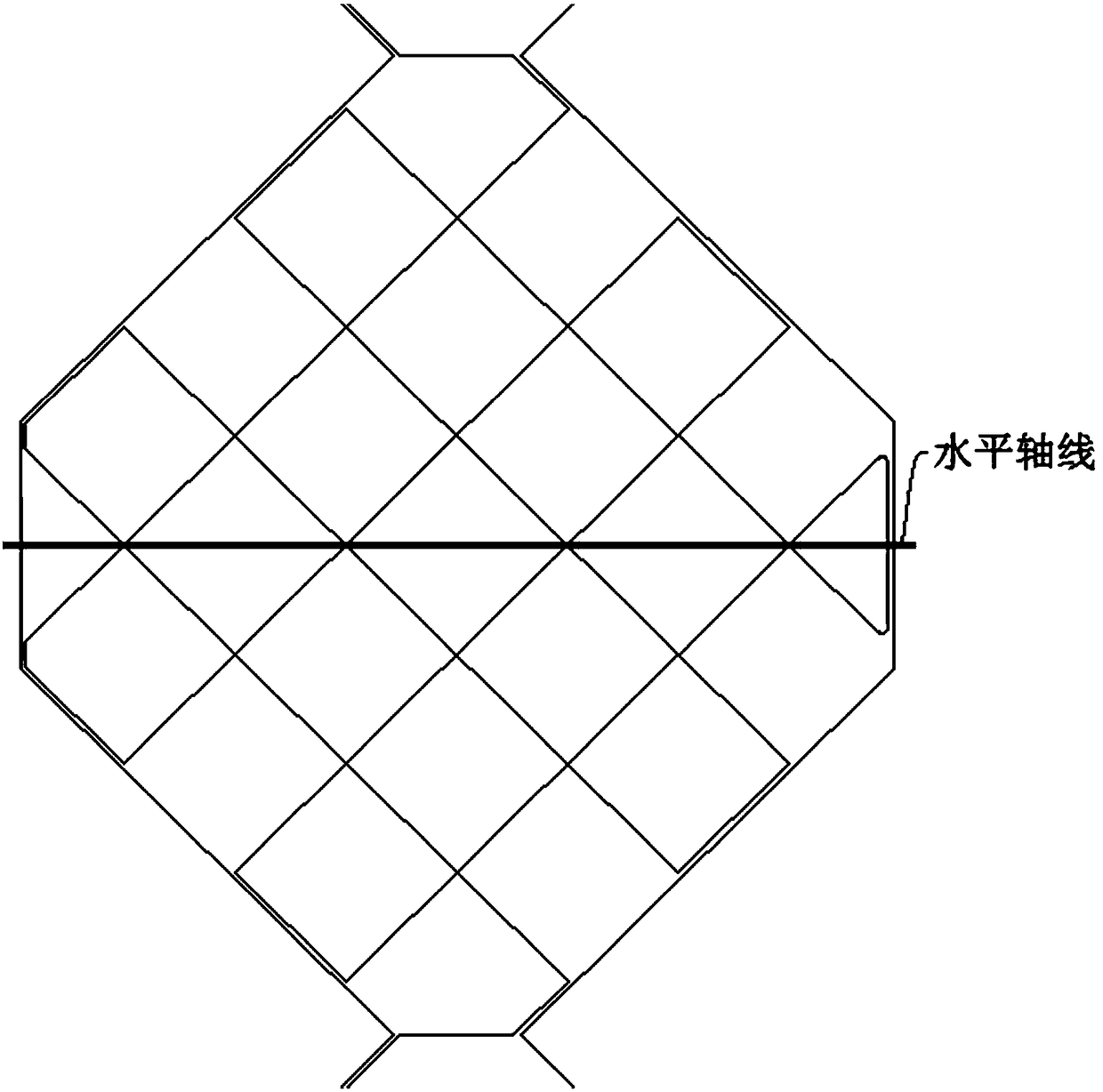
[0031] Such as image 3 with Figure 4 As shown, this embodiment relates to a touch screen laser splicing pattern structure, including a first etching line 1 and a second etching line 2 adjacent to it, and the first etching line 1 and the second etching line 2 pass through the first right angle at the splicing point The bending structure is connected; the first right-angle bending structure is a first open rectangle 5, including two parallel etching lines and an etching line perpendicular to and connected to the two parallel etching lines;

[0032] The extension of the first etching line 1 and the second etching line 2 intersects at an intersection angle α.

[0033] This embodiment also includes a third etching line 3 and a fourth etching line 4 adjacent to it, the third etching line 3 and the fourth etching line 4 are connected by a second right-angle bending structure at the joint; the second right-angle The bent structure is a second open rectangle 6, including two parall...

Embodiment 2

[0040] Such as Figure 5 As shown, this embodiment relates to a touch screen laser splicing pattern structure, including a first etching line 1 and a second etching line 2 adjacent to it, and the first etching line 1 and the second etching line 2 pass through the first right angle at the splicing point The bending structure is connected; the first right-angle bending structure is a first open rectangle 5, including two parallel etching lines and an etching line perpendicular to and connected to the two parallel etching lines;

[0041] The extension of the first etching line 1 and the second etching line 2 intersects at an intersection angle α.

[0042] This embodiment also includes a third etching line 3 and a fourth etching line 4 adjacent to it, the third etching line 3 and the fourth etching line 4 are connected by a second right-angle bending structure at the joint; the second right-angle The bent structure is a second open rectangle 6, including two parallel etching line...


PUM


Abstract

The invention relates to a touch screen laser spliced pattern structure and an etching wiring method thereof in the technical field of a touch screen. A first etching wire is connected with an adjacent second etching wire at a spliced position by a first right angle bent structure; extension lines of the first etching wire and the second etching wire intersect with each other; and an intersectionangle is alpha. According to the invention, the right angle transition splicing structure is added at the oblique line splicing position, so that splicing accuracy of oblique line segments can be ensured, and a short circuit caused by splicing deviation is avoided.

Description

technical field [0001] The invention relates to a technology in the field of touch screens, in particular to a touch screen laser splicing pattern structure and an etching wiring method thereof. Background technique [0002] Such as Figure 1A with 1B Shown are the laser pattern structure diagrams of the ITO upper film and lower film in the touch screen, respectively. The ITO pattern unit in the touch screen adopts the laser process, but the distance of the laser once is limited and needs to be spliced, so it is impossible to realize such Figure 1C Ideal for etched wire routing. There is a problem of splicing deviation in the direct splicing of oblique lines and oblique lines by laser machines, and this splicing deviation will cause local short circuits. At present, most of the ITO pattern units adopt a rhombus structure, which inevitably needs to be spliced ​​with oblique lines, such as figure 2 shown. Contents of the invention [0003] Aiming at the above-mentione...

Claims


Application Information

Patent Timeline
Patent Type & Authority Applications(China)
IPC IPC(8): G06F3/041
CPCG06F3/041G06F2203/04103
Inventor 李文李兆勇任小勇
Owner ZHANGJIAGANG KANGDE XIN OPTRONICS MATERIAL
Why Eureka
Try Eureka