
High-voltage resistance circle detection equipment

A technology of high-voltage resistance and equipment, which is applied in the field of high-voltage automatic detection equipment for products, can solve the problems of poor detection of detection equipment, inconvenient repair/maintenance, cumbersome transfer/transfer, etc., and achieve low misjudgment rate of product detection and mechanization And the effect of high degree of automation and small footprint

Pending Publication Date: 2018-06-15
CENT POINT TESTING & TECH
View PDF14 Cites 0 Cited by
  • Summary
  • Abstract
  • Description
  • Claims
  • Application Information

AI Technical Summary

Problems solved by technology

[0004] However, the shortcomings of the above-mentioned high-voltage automatic detection equipment are: first, the equipment is bulky, occupies a large area, and repair / maintenance is inconvenient, and the transfer / transfer is cumbersome; second, the detection capacity of the above-mentioned detection equipment is not good; The third is that the high-voltage electrodes of the above-mentioned detection equipment are set in the water tank, which may easily cause high-voltage electric leakage, and there are hidden dangers of safety accidents

Method used


Image

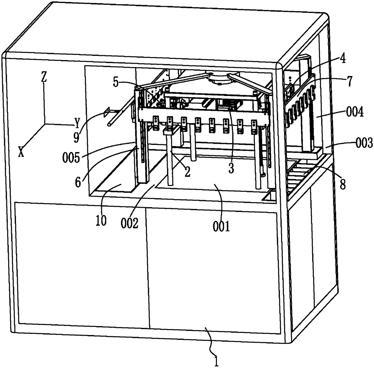
  • High-voltage resistance circle detection equipment
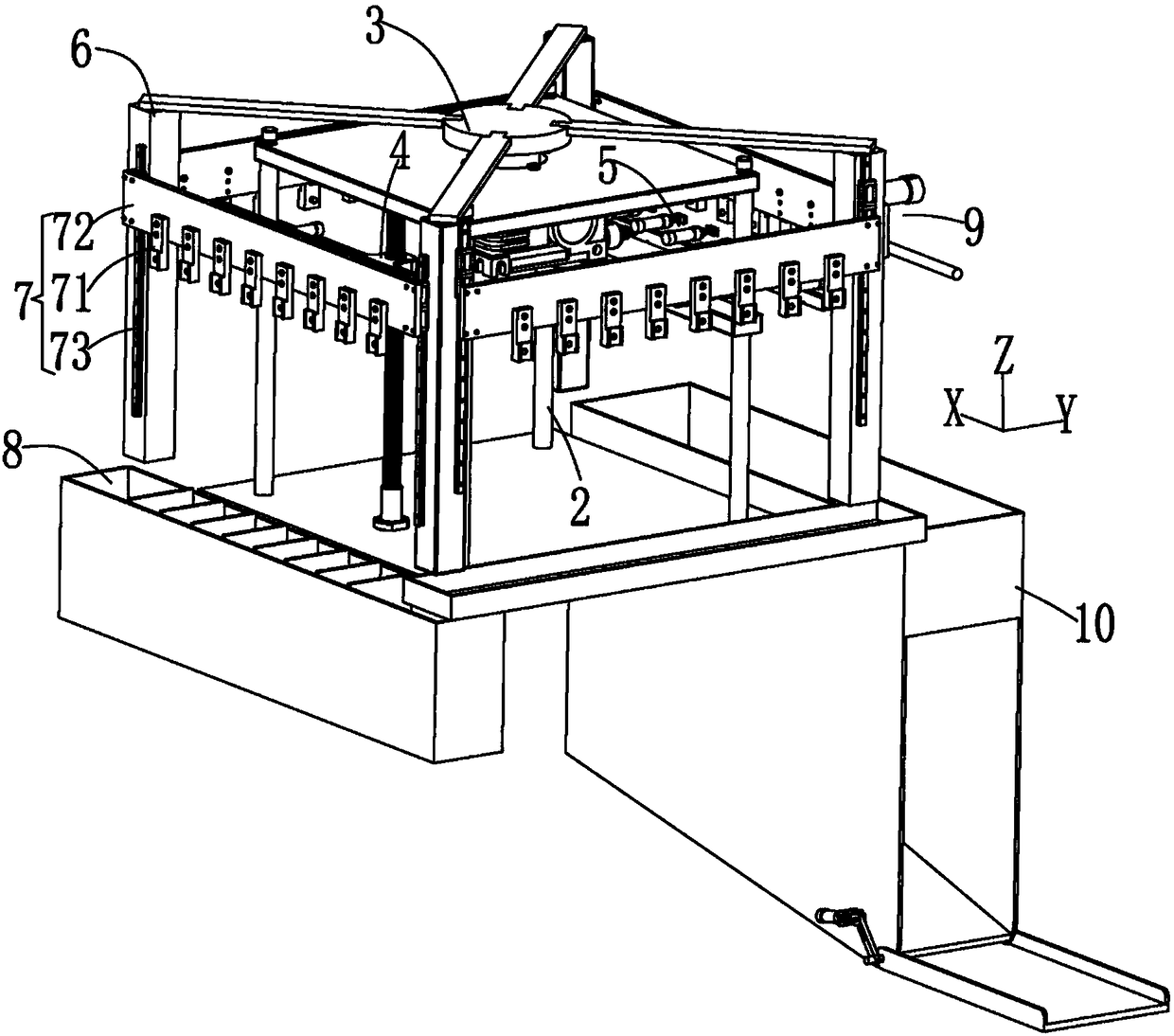
  • High-voltage resistance circle detection equipment
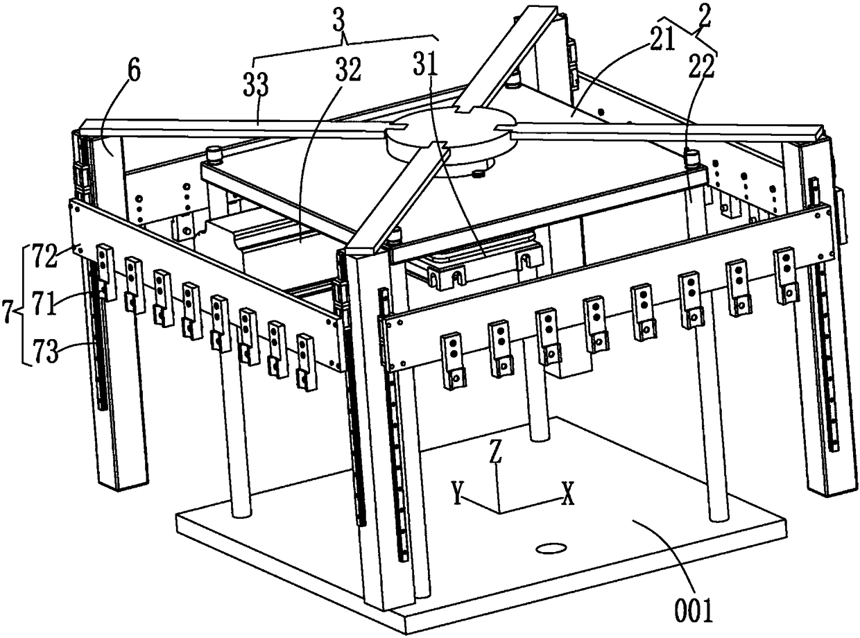
  • High-voltage resistance circle detection equipment

Examples


Embodiment Construction

[0025] The present invention will be described in further detail below in conjunction with the accompanying drawings.

[0026]The embodiments described by referring to the figures are exemplary and are intended to explain the present application and should not be construed as limiting the present application. In the description of the present application, it should be understood that the terms "center", "longitudinal", "transverse", "length", "width", "thickness", "upper", "lower", "front", " Orientation or position indicated by "back", "left", "right", "vertical", "horizontal", "top", "bottom", "inner", "outer", "clockwise", "counterclockwise", etc. The relationship is based on the orientation or positional relationship shown in the drawings, and is only for the convenience of describing the present application and simplifying the description, rather than indicating or implying that the referred device or element must have a specific orientation, be constructed and operated i...


PUM


Abstract

The invention discloses high-voltage resistance circle detection equipment which comprises a rack. The rack is provided with a rotation assembly, a lift assembly and a pushing assembly. The rotation assembly is connected with a square rotation base. The four side surfaces of the square rotation base are respectively provided a hanger assembly. Each hanger assembly comprises magnetic hangers in horizontal / vertical arrangement. The rotation assembly can drive the square rotation base and the hanger assemblies to realize intermittent rotation, and cooperatively drive products adsorbed on the magnetic hangers to rotate among a loading station, a test station, a draining station and an unloading station. The lift assembly and the pushing assembly are arranged on the test station and the unloading station respectively. The lift assembly is movably docked to the hanger assembly rotated to the test station, and the magnetic hangers of the hanger assembly are electrically connected with a high-voltage power supply. The lift assembly can drive the hanger assembly to carry products to be vertically and lively immersed into or removed out of water tanks to realize high-voltage resistance testcooperatively. The pushing assembly can reject products carried by the hanger assembly rotated to the unloading station in a classified manner, and cooperates with a material stop assembly to finish unloading of qualified products / defective products.

Description

technical field [0001] The invention relates to the field of high-voltage automatic detection equipment for products, in particular to high-voltage continuous inspection equipment for products (such as screwdrivers, pliers, wrenches, knives, etc.). Background technique [0002] Electricians need live work in many occasions to avoid various effects caused by power outages. The main tools necessary for electrician live work include screwdrivers, pliers, wrenches, knives and other products. In order to ensure the personal safety of electricians working with live electricity, most of the screwdrivers must be insulated except for the blade head, be able to withstand high voltage, and not be broken down by high voltage (such as 10kv high voltage). The same goes for products like pliers, wrenches, knives, etc. Therefore, before products such as screwdrivers, pliers, wrenches, and knives leave the factory, product inspection must be carried out on them, and the products can only l...

Claims


Application Information

Patent Timeline
Patent Type & Authority Applications(China)
IPC IPC(8): G01R31/18B07C5/344
CPCG01R31/18B07C5/344
Inventor 潘莉黛占志亮刘长利丁鹏
Owner CENT POINT TESTING & TECH
Learn More