Gap-adjustable grate plate for cooling machine

A gap and grate technology, applied in the field of adjustable gap cooler grate plate, can solve the problem of non-adjustable ventilation gaps, achieve the effect of reducing spare parts specifications, reducing production costs, and broadening market prospects

Pending Publication Date: 2018-06-15
NANJING KISEN INT ENG
View PDF6 Cites 7 Cited by
  • Summary
  • Abstract
  • Description
  • Claims
  • Application Information

AI Technical Summary

Problems solved by technology

[0006] In order to overcome the deficiencies of the prior art, the present invention provides an adjustable slit cooler grate plate, which solves the problem that the ventilation slits of the conventional cooler grate plate cannot be adjusted, greatly improves the scope of application of the grate plate, and reduces production and maintenance cost

Method used


Image

  • Gap-adjustable grate plate for cooling machine
  • Gap-adjustable grate plate for cooling machine

Examples


Embodiment 1

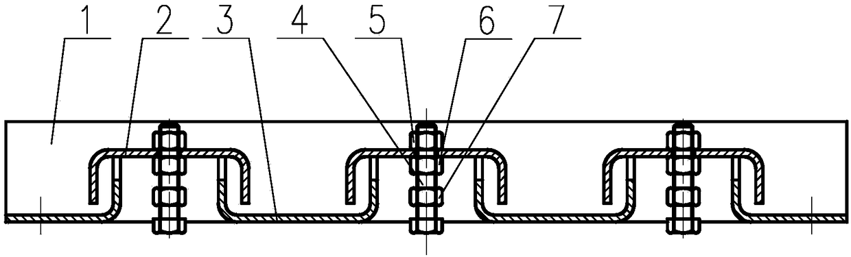
[0017] Reference figure 1 , The preferred embodiment 1 of the present invention provides a grate board for an adjustable gap cooler, which includes a grate board body 1, and also includes a plurality of fixed plates 3 and a moving plate 2, the fixed plates 3 are arranged at intervals on the same horizontal plane and fixed on On the grate board body 1, the moving plates 2 are sequentially arranged between the adjacent fixed plates 3, and the width of the moving plate 2 is greater than the distance between two adjacent fixed plates 3, and the moving plate 2 is fixed to its two sides. A ventilation gap is formed between the plates 3, and the movable plate is fixed on the adjusting mechanism and can be moved up and down through the adjusting mechanism.

[0018] Specifically, the adjusting mechanism includes an adjusting bolt 4 and a fixing nut 7 that cooperate with each other, and the fixing nut 7 is fixedly connected to the wall panel body 1, and the adjusting bolt 4 is provided with...

Embodiment 2

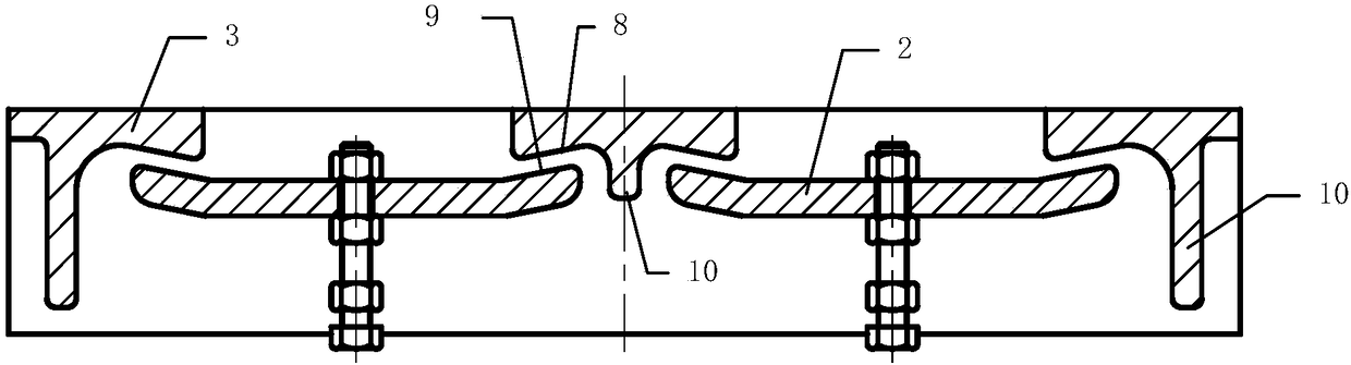
[0022] Reference figure 2 The preferred embodiment 2 of the present invention provides an adjustable gap cooler grate plate. The difference from embodiment 1 is that the fixed plate 3 is arranged above the moving plate 2, and the fixed plate 3 is provided with vertical For the downward protrusion 10, the height of the protrusion on the fixing plate on both sides of the wall plate body is greater than the height of the protrusion on the fixing plate in the middle of the wall plate body.

[0023] The lower side of the fixed plate on both sides of the protrusion 10 is a fixed inclined surface 8. The height of the fixed inclined surface 8 near the protrusion is higher than the height of the side away from the protrusion. The movable inclined surface 9 forms a ventilation gap with the fixed inclined surface 8, and the movable inclined surface 9 is an inclined surface with a high outer side and a low inner side. The ventilation slit of the specific structure formed in this embodiment...


PUM


Abstract

The invention provides a gap-adjustable grate plate for a cooling machine. The grate plate comprises a grate plate body and further comprises a plurality of fixed plates and movable plates, the fixedplates are sequentially arranged on the same horizontal plane at intervals and are fixed on the grate plate body, the movable plates are sequentially arranged between the adjacent fixed plates, the width of each movable plate is bigger than the distance between every two adjacent fixed plates, ventilation gaps are formed between the movable plates and the fixed plates on the two sides of the movable plates, and the movable plates are fixed on an adjusting mechanism and can move up and down through the adjusting mechanism; and the adjusting mechanism comprises adjusting bolts and fixing nuts which are matched with each other, the fixing nuts are fixedly connected with a wall plate body, locking nuts and limiting nuts are arranged on the positions, on the upper sides and the lower sides of the movable plates, of the adjusting bolts correspondingly, and the limiting nuts are fixedly connected with the adjusting bolts. According to the grate plate, in actual use, the gap of the grate platecan be freely adjusted to change cooling air volume, and the grate plate does not need to be replaced, so that the maintenance cost is reduced, and the grate plate has a wide market prospect.

Description

Technical field [0001] The invention relates to the technical field of cooler grate plates for the cement industry, in particular to an adjustable gap cooler grate plate. Background technique [0002] An important function of the grate plate of the cooler in the cement industry is to provide a suitable cooling air gap (including the size of the gap and its distribution on the grate plate), so that the cooling air enters the clinker to be cooled in a reasonable way and wind speed, and the clinker Cool sufficiently. [0003] In actual operation, affected by the rotary motion of the rotary kiln, the clinker falling on the grate bed is segregated. The coarse and fine materials are located on both sides of the grate bed, and the thickness of the material layer on the grate bed is not uniform. In order to cool the clinker particles uniformly, the thick material layer area and the fine material side should be given more cooling air volume, and the thin material layer and the coarse mater...

Claims


Application Information

Patent Timeline
Patent Type & Authority Applications(China)
IPC IPC(8): F27D15/02C04B7/47
CPCF27D15/022C04B7/47F27D2015/0246
Inventor 李帅波徐靖李立华胡斌王小祥
Owner NANJING KISEN INT ENG
Why Eureka
Try Eureka