
Efficient solar heat collector

A technology of solar collectors and solar collector tubes, which is applied in the field of heat collectors, can solve the problems that the heat collection efficiency cannot reach the highest value, the direct heating area of ​​the working medium is limited, and the heat absorption efficiency of the heat collector is affected, so as to improve the heat collection efficiency , Improve operating efficiency and increase speed

Inactive Publication Date: 2018-06-15
河南百年融熥实业有限公司
View PDF6 Cites 1 Cited by
  • Summary
  • Abstract
  • Description
  • Claims
  • Application Information

AI Technical Summary

Problems solved by technology

Although the vacuum flat-plate solar collector can convert solar energy into heat energy, because its light absorption heat exchange plate is composed of a working medium heat transfer circulation tube and a heat exchange plate, the direct heating area of ​​the working medium is limited, and The heat at the far end of the heat exchange plate needs to pass through a certain path to transfer heat to the working fluid heat transfer circulation tube, which affects the overall heat absorption efficiency of the collector
[0005] In addition, traditional solar collector tubes or vacuum flat solar collectors have a certain lack of heat collection efficiency in consideration of aesthetics, craftsmanship or other factors, resulting in a failure to achieve the highest heat collection efficiency. Therefore, it is urgent to explore a A kind of solar heat collecting tube that reasonably arranges the solar heat collecting tube and satisfies the requirements of aesthetics and craftsmanship, so that it can achieve the ultimate heat collecting efficiency and greatly improve the efficiency of absorbing solar energy, so as to provide cleaner and green energy for human life, as much as possible Solve the contradiction between people's growing needs for a better life and unbalanced and inadequate development in terms of solar energy utilization

Method used


Image

  • Efficient solar heat collector
  • Efficient solar heat collector
  • Efficient solar heat collector

Examples


Embodiment Construction

[0028] In order to make the purpose, technical solution and advantages of the present invention clearer, the technical solution of the present invention will be described in detail below. Apparently, the described embodiments are only some of the embodiments of the present invention, but not all of them. Based on the embodiments of the present invention, all other implementations obtained by persons of ordinary skill in the art without making creative efforts fall within the protection scope of the present invention.

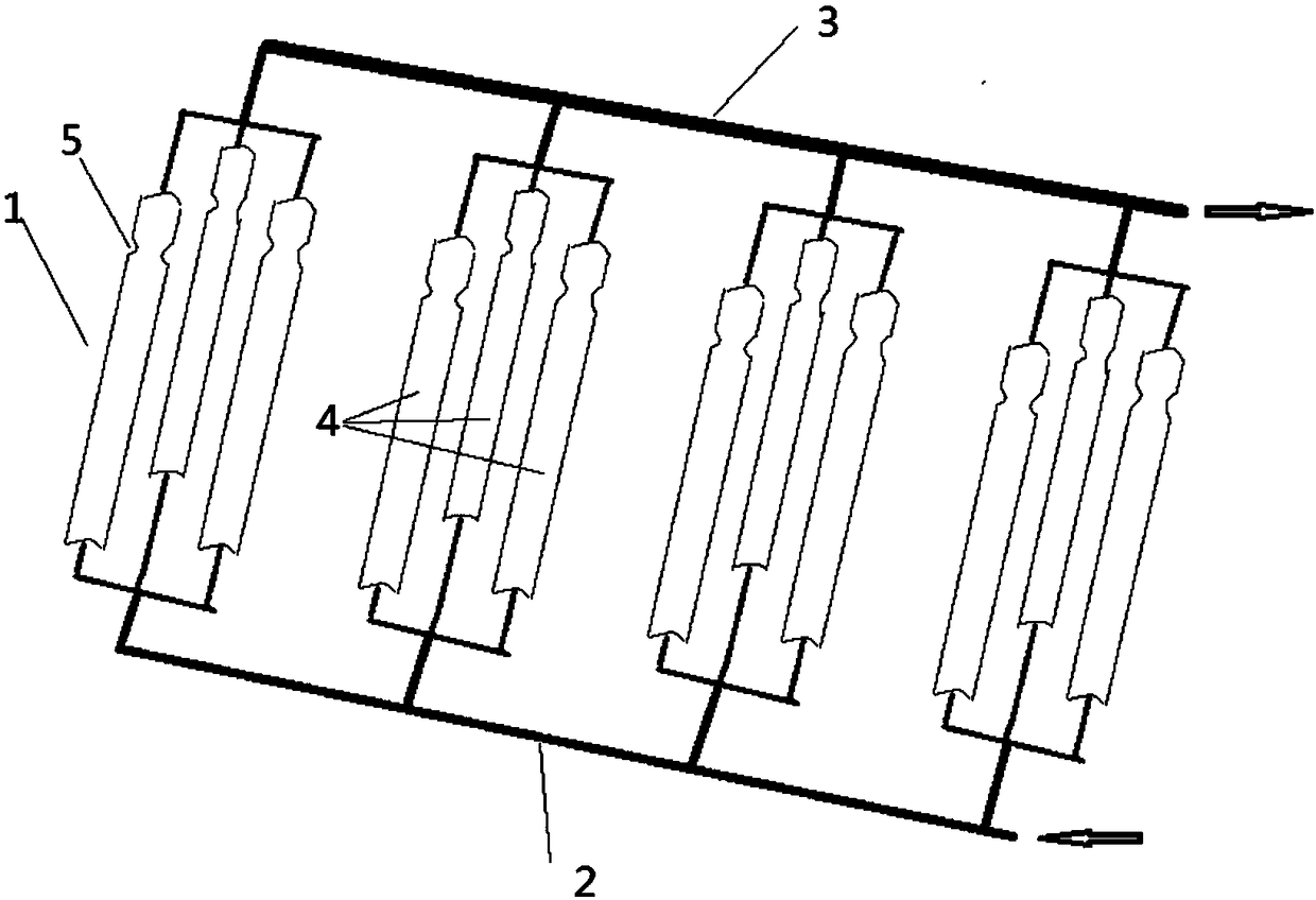
[0029] Such as Figure 1-2 Shown, a kind of high-efficiency solar heat collector, it comprises a plurality of solar heat collection tube bundles 1, and the inlet header 2 and the outlet header 3 that connect a plurality of solar heat collection tube bundles, and a plurality of solar heat collection tube bundles 1 are closely Arranged side by side between the inlet header 2 and the outlet header 3, it is characterized in that each solar collector tube bundle 1 i...


PUM


Abstract

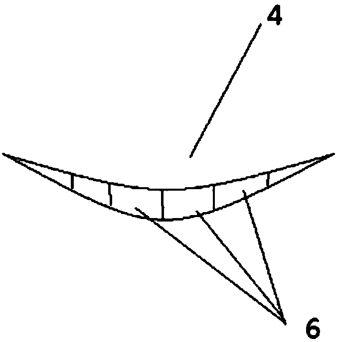
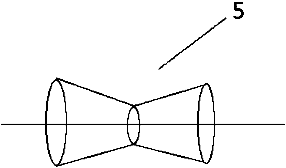
The invention provides an efficient solar heat collector. The collector comprises a plurality of solar heat collecting pipe bundles, and an inlet collecting pipe and an outlet collecting pipe which are connected with the plurality of solar heat collecting pipe bundles; the plurality of solar heat collecting tube bundles are closely arranged between the inlet collecting pipe and the outlet collecting pipe side by side; the collector is characterized in that each solar heat collection tube bundle comprises at least three solar heat collecting pipes, the three solar heat collecting pipes are correspondingly connected with the inlet collecting pipe and the outlet collecting pipe through confluence devices and are arranged in a triangular shape, and the cross section of each solar heat collecting pipe is in a crescent shape and is formed by combining a front concave surface and a rear concave surface; and the cross section of the portion in the upper half part of each solar heat collectingpipe in height is shrunk and then expanded so as to form a shrinkage-expansion section.

Description

technical field [0001] The invention relates to a heat collector, in particular to a high-efficiency solar heat collector. Background technique [0002] With the development of civilization, the use of fossil fuels has increased dramatically, which has led to serious environmental pollution problems and global warming, which has become a hot topic in the international community. dissenting views related to national interests are going in an undesired direction. Accordingly, various attempts to develop new renewable energy have been made to actively cope with global warming and environmental problems. New renewable energy refers to energy that is utilized by converting traditional fossil fuels or utilizing renewable energy including sunlight, water, geothermal, and biological organisms. Its characteristics are future energy for sustainable energy supply systems. The importance of new renewable energy has grown due to unstable oil prices and restrictions on climate change a...

Claims


Application Information

Patent Timeline
Patent Type & Authority Applications(China)
IPC IPC(8): F24S10/70F24S80/30
CPCY02E10/44
Inventor 杨德权
Owner 河南百年融熥实业有限公司
Learn More